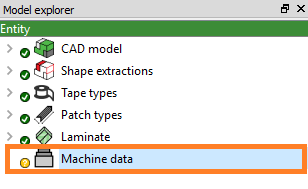
The Patch laminate is the root element in the hierarchical structure i.e laminate -> stack -> layer -> sublayer -> chain -> patch.
To create a laminate, follow the following steps:
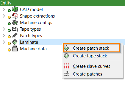
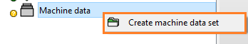
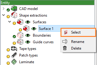
Create patch stack
Right click on Laminate and then click on Createpatchstack.
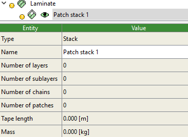
Stack is created with the name Stack 1 and entities as shown:
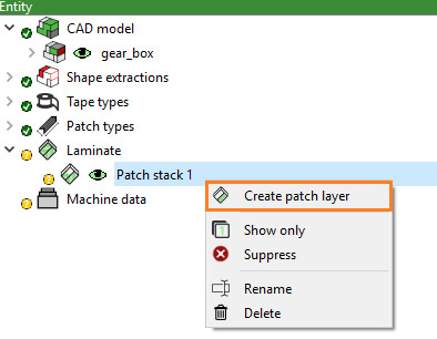
Create patch layer
Right click on Stack 1 and then click on Createpatchlayer.
Layer is created with the name layer 1.
Generating layup
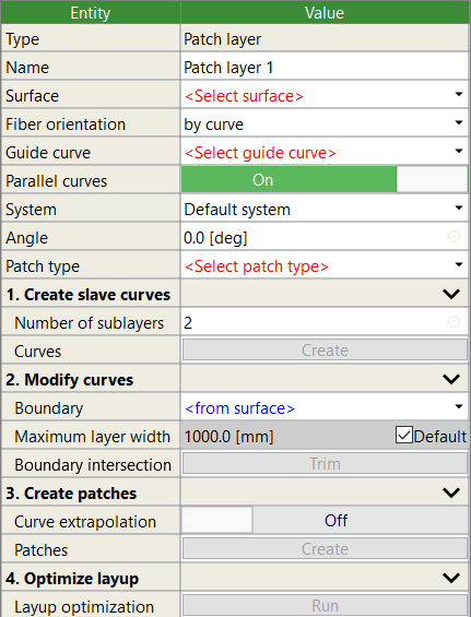
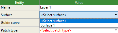
Property window of the created layer (Layer 1) as shown below consists of various entities for generating layup.
Follow this step-by-step approach to generate layup in Patch Artist:
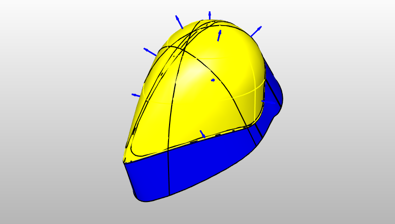
Click on the entity Surface and select a surface from the drop-down list where you want to generate Slave curves.
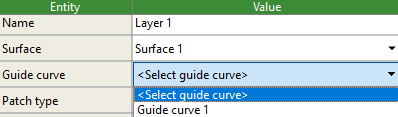
Click on the value of next entity Master curve and select Master curve from the drop-down list.
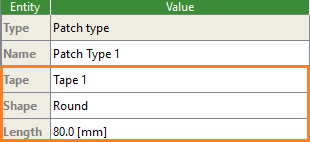
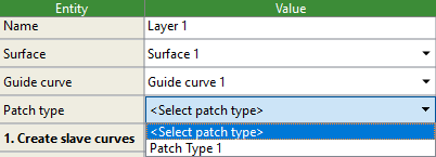
Click on the value of entity Patch type and select a patch type from the drop-down list which you have created previously.
Create Slave curves
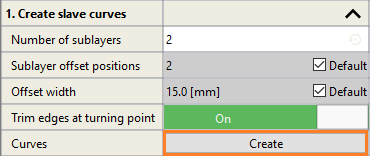
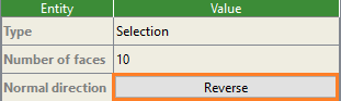
Click on the drop-down button to change default parameters of Slave curves. Enter the values for Number of sublayers, Sublayer offset positions, Offset width and turn On or Off Trim edges at a turning point and then click on the Create button.
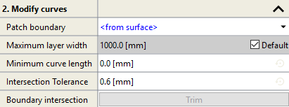
Modify curves
Enter the appropriate values for the entities Maximum layer width, Minimum curve length, Intersection Tolerance. After this click outside property window or click enter to modify Slave curves.
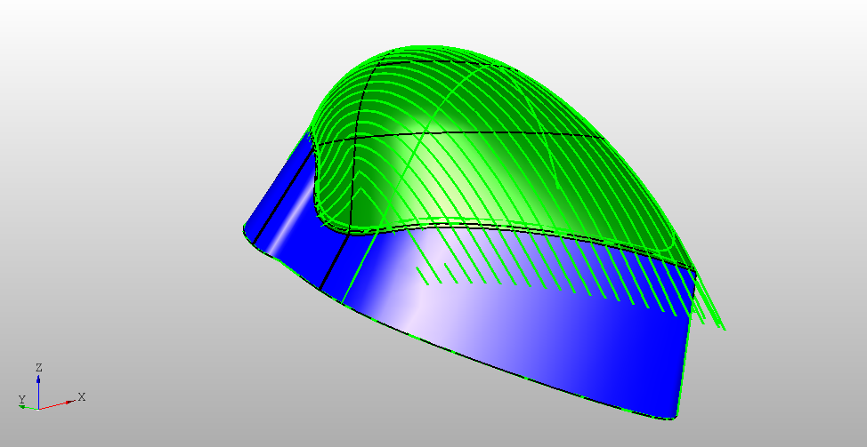
Slave curves are created as shown in the figure below:
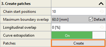
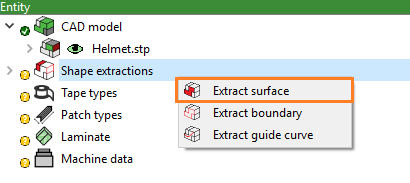
Create patches
Click on the drop-down button to make changes in the default settings and click on the Create button to generate patches.
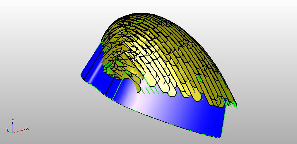
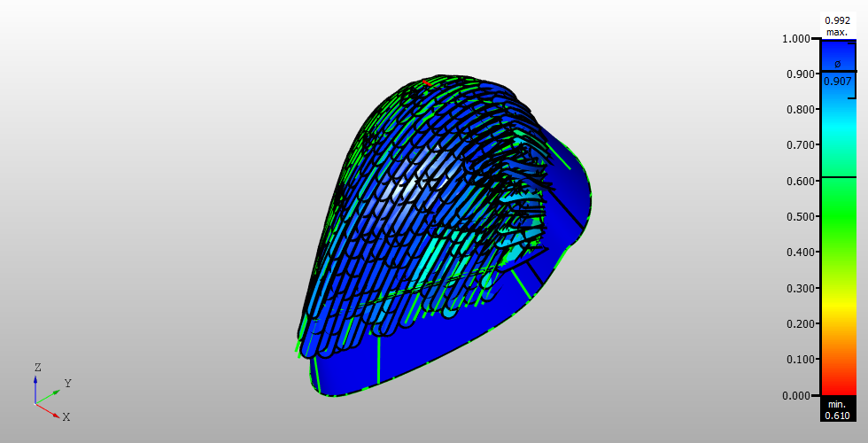
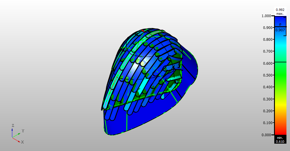
Patches are generated as shown below:
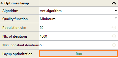
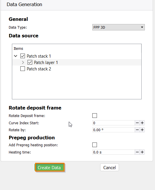
Optimize layup
Click on the Run button to optimize the layup. You can make changes here depending on the requirements and quality required.
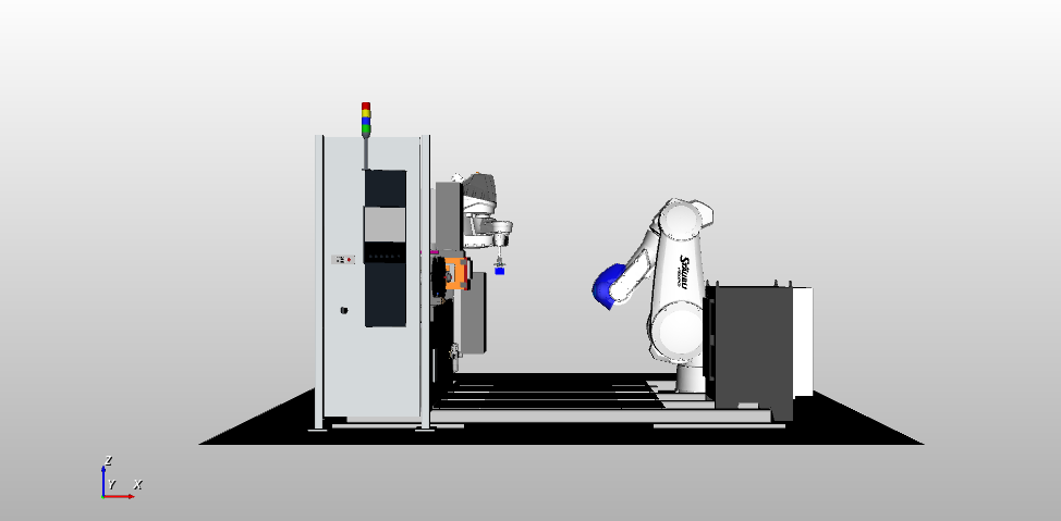
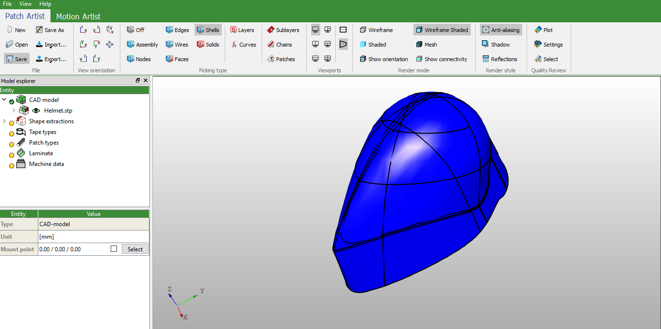
View simulation of the robot movements by playing Motioncontroller from Ribbon bar. You can visualize how positioner and picker axes are generating layups on the CAD model.
 .
.