8. CAD data
8.1. Exporting patch laminate to CAD formats
For patch laminates, it is sometimes necessary to export the geometry of some patches to an external CAD format for analysis.
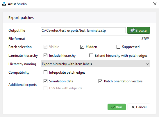
This can be done by choosing the Export patches entry in the export menu (Export the CAD model), which will open the following dialog:
8.1.1. Patch export settings
The following settings are avialable in the Export patches dialog:
Output file - Location and name of the resulting file
File format - The file format will be automatically identified based on the output file extension
Patch selection - Identifies which patches should be exported
Visible: Adds all visible patches to the exported set
Hidden: Adds all hidden patches to the exported set
Suppressed: Adds all suppressed patches to the exported set
Laminate hierarchy - Defines the hierarchical structure of the exported CAD file
Include hierarchy: Exports the patches in a hierarchy matching the laminate hierarchy in Artist Studio (currently available only for STEP files)
Extend hierarchy with patch edges: Makes the hierarchy one level deeper, identifying each patch edge separately
Hierarchy naming - Defines how the hierarchy levels in the export should be named
…with item labels: Uses fully-qualified identifying labels for each item in the hierarchy
…with item names: Uses the names of the stacks/layers/…/patches as they are shown in the Artist Studio model explorer
Compatibility - Options for compatibility with external software
Interpolate patch edges: Reduces each patch edge to a single geometric element by interpolation. May result in less accurate patch geometry.
Additional exports - Additional geometry and/or extra metadata to be included in the export
Simulation data - Includes the necessary geometry and metadata for use in the HyperMesh Plugin (requires laminate hierarchy with item labels)
Patch orientation vectors - Includes patch orientation vectors as sub-elements of each patch
CSV file with edge ids - Exports an additional .csv file which identifies each patch edge and its parents in the hierarchy
8.2. Generate Master Curve using external CAD software
Sometimes there is a need to generate Master Curve specifically to the particular design. The user can generate their own Master Curves by using external CAD softwares such as:
Inventor ( ask about more softwares)
Solidworks
CATIA v5
…
8.2.1. Generate Master Curve using Inventor
Autodesk Inventor, developed by U.S. based software company Autodesk, is a computer-aided design application for creating 3D digital prototypes used in the design, visualization and simulation of products.

For the generation of Master Curve using Inventor follow these steps:
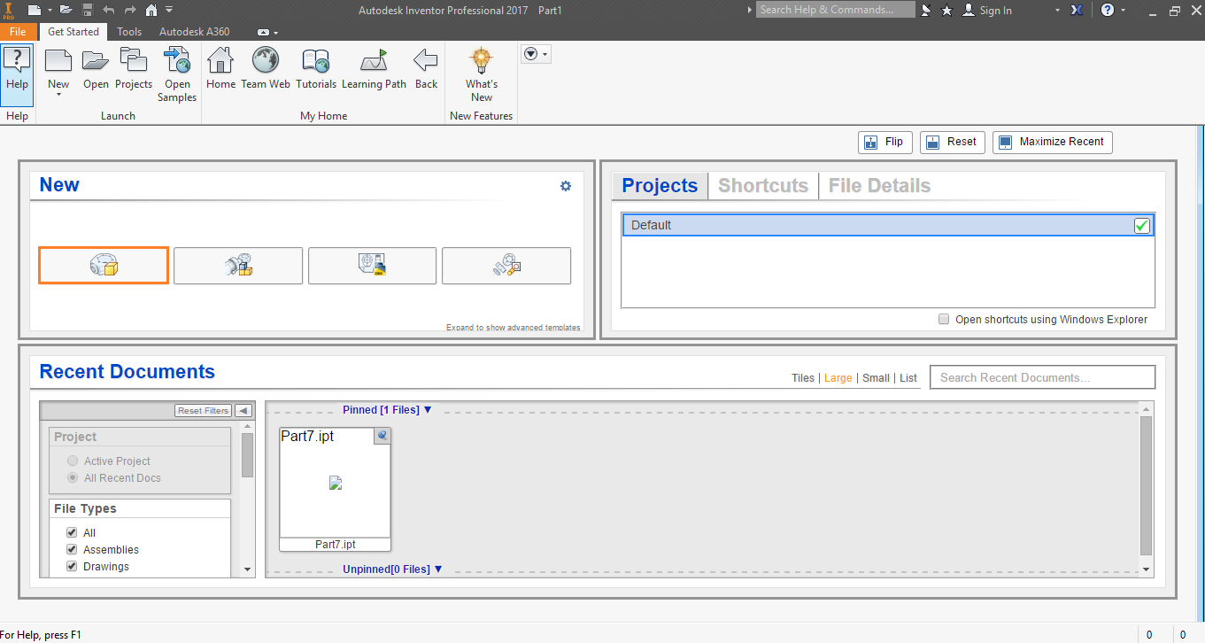
Open Inventor.
Select New Part under New group or press CTRL+N.
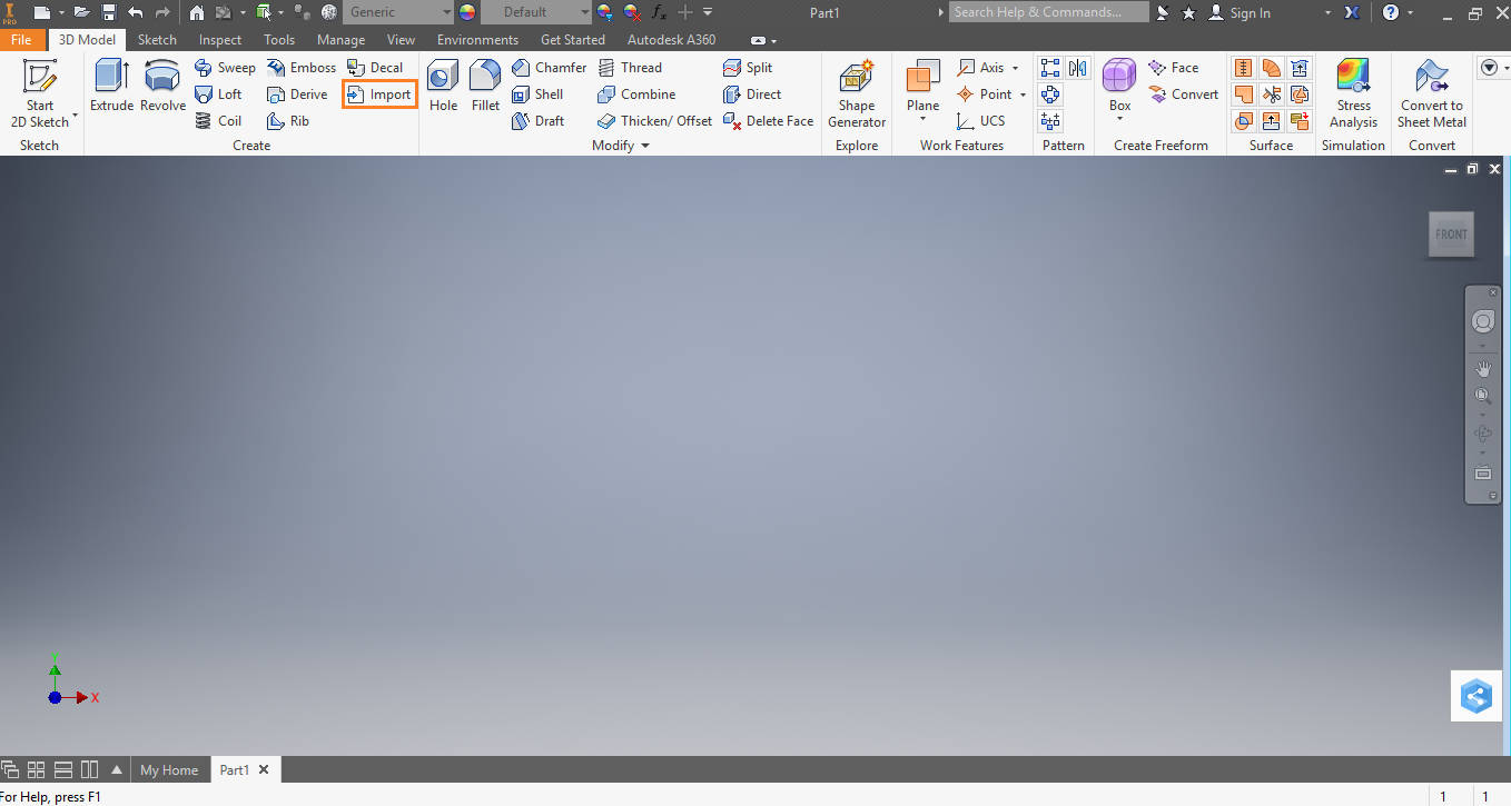
Click on Import from the Create group as shown below:
Browse to select the file and click on Open.
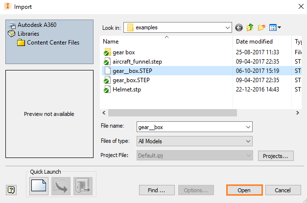
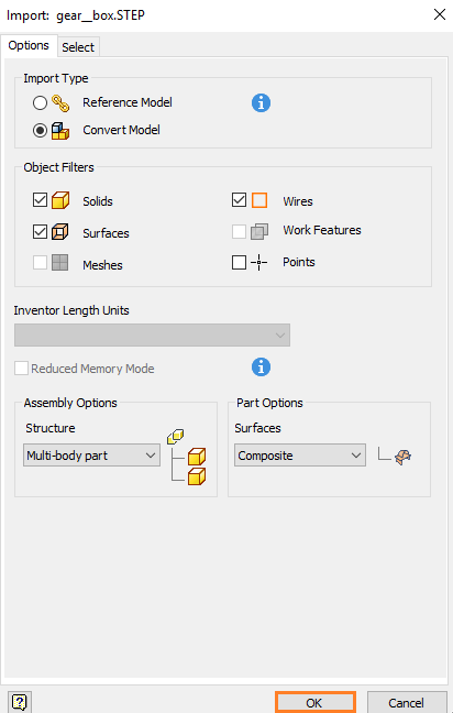
A pop-up will appear on the screen > click on Ok.
The file, gear__box.step, is now imported into the session.
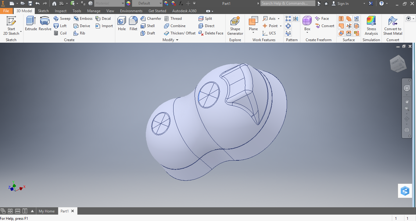
Click on the drop down button from the Sketch group and select Start 3D Sketch.

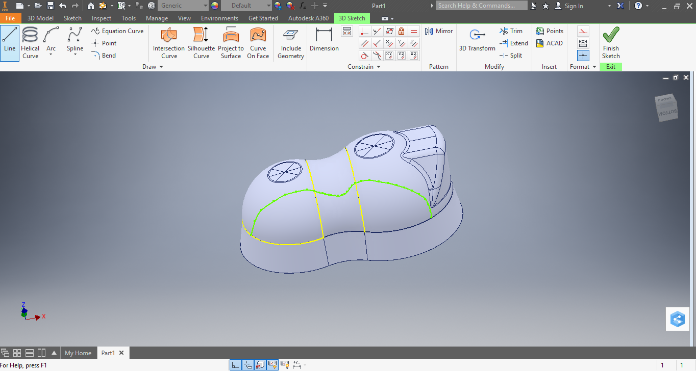
Select Curve on Face from the group Draw to draw a spline onto the surface.

Decide a Starting point for Master Curve and click on the surface. With every click a spline would be created by joining the two points as shown:
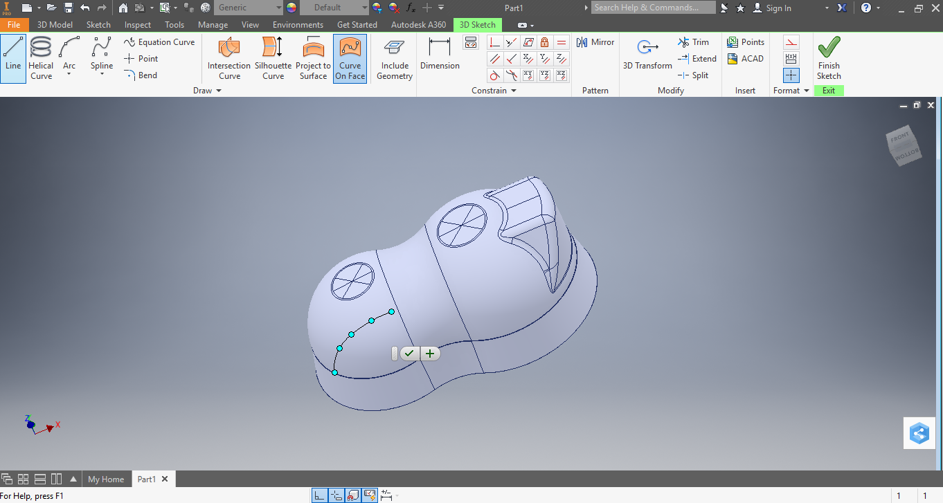
After finishing with the desired Master Curve, click on the OK button.
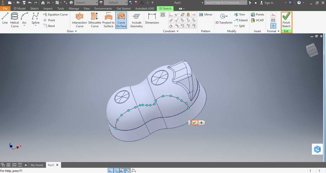
Master Curve is now created on the surface.
