2. Basics
This chapter introduces the placement process and the structure of the created laminates.
2.1. Fiber Patch Placement
Fiber Patch Placement (FPP) is an additive manufacturing technology for the automated production of geometrically complex fiber composites and curvilinear reinforcements. The FPP process is based on the application of fiber patches. A patch is defined as a cut piece of a tape.
The Fiber Patch Placement process can be summarized in the following steps:
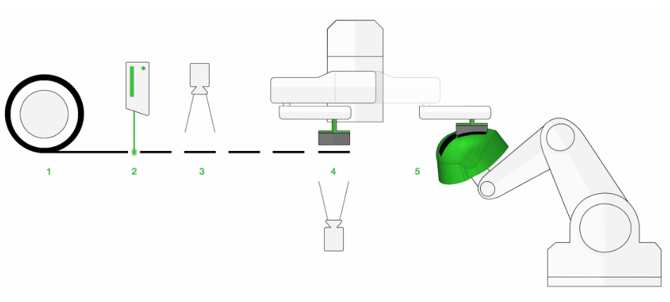
Fig. 2.1 Fiber Patch Placement process
Feed fiber tape
Cut fiber tape into patches
Inspect fiber patch quality
Pick up patch, check patch position
Position patch on 3D preforming tool
The tape is specified by filament material, fiber titer, width, areal weight and binder material. In the simplest case, the cutting geometry is straight and perpendicular to the sides of the patch. With the laser cutting technology, it is possible to produce patches with complex cutting edges. Even curvilinear and uneven cutting geometries that vary throughout the process can be achieved.

Fig. 2.2 Patch definition
Rectangular patches lead to gaps and overlaps which can affect the strength and the thickness of a laminate. To avoid this, rounded cutting edges can be used to reduce these effects. Fig. 2.3 illustrates this.
Additionally, variable patch lengths can further increase strength by reducing the number of gaps while increasing production speed.
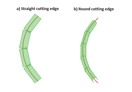
Fig. 2.3 Influence of cutting edges on overlaps
2.2. Laminate structure
Artist Studio uses a discontinuous patch approach to build a laminate. Patches are organized hierarchically in containers to reduce complexity. This allows for flexible and fast editing of the laminate. The hierarchical structure of the Laminate structure of FPP is shown as follows:

Fig. 2.4 Laminate hierarchy
The laminate is the root element in this hierarchical structure. It exists only once in every project and contains all the entities. The next (hierarchically) lower level is called stack. A stack describes the positioning properties of all the layers it contains. Advancing further down the hierarchy the level of layers describes a layup of multiple patches that can be defined by common properties. In addition to their inherent properties, they usually refer to CAD entities like surfaces, lines or points.
2.3. Structural layers
Structural layers imitate the behavior of traditional fiber reinforced composites consisting of several unidirectional plies. A structural layer generally consists of the surface to be (partially) covered with patches and one or several curves describing the local orientation and possible positions of the patches. It consists of several sublayers. An individual sublayer fully covers the surface but there is no overlap between its patches. Therefore they are not capable of transmitting forces. This can only be achieved by using several overlapping sublayers which are shifted against each other.
Sublayers themselves are organized in chains as shown in Fig. 2.5. A chain is formed by several patches aligned together edge to edge (short edges) along a curve. The distribution of gaps between adjacent sublayers strongly influences the strength of a structural layer. To achieve a high laminate strength, Patch Artist offers a patch overlap optimization.

Fig. 2.5 Structural layers
2.4. Patch boundaries
The CAD model must at least have a boundary line enclosing the area that is supposed to be filled with patches. This is known as a Patch boundary. By default, the boundary of the extracted surface is treated as a patch boundary by Artist Studio. Moreover, one can also specify their own patch boundary depending on the requirements.
2.5. Curves
Artist Studio supports the curve creation process with two algorithms: One for creating parallel offset curves from a base curve and the other for integrating isogonal curves from seed points. Both algorithms have different characteristics and fields of application.
2.5.1. Parallel curves
In order to create a laminate without gaps and overlaps it is beneficial to use a set of parallel curves as a base. This comes with the drawback of not being able to follow a prescribed fiber orientation in the case of a general base surface.
The user must provide at least one Master curve per layer. Patch Artist is able to create so called Slave curves as parallel offsets from the Master curve, covering the area inside the patch boundary. This is illustrated below:

Fig. 2.6 Creation of parallel curves
a) Master curve is extracted from the surface.
b) Creation of parallel Slave curves with constant offset distance w based on Master curve.
2.5.2. Isogonal curves
In order to create a laminate in which all fibers are oriented along a predefined fiber orientation isogonal curves have to be used. In the general case, a set of such curves will not be parallel. Therefore - depending on the surface curvature - gaps and overlaps may occur. The creation process is depicted in Fig. 2.7.

Fig. 2.7 Creation of isogonal curves
a) Extract a Master curve from the surface and define the fiber orientation. Notice the bump on the otherwise flat surface.
b) Create seed points on the Master curve. The distance between two seed points equals the tape width w.
c) Integration of Slave curves based on seed points and local projection of fiber orientation onto surface. Notice the the nonparallel curves in vicinity of the bump.
2.5.3. Curve extrapolation
There are parts for which it is necessary to create a laminate with constant thickness up to the edges of the tooling. For general boundaries a linear extrapolation of the curves is necessary. This results in curves outside the geometry surface. Those curves outside the geometry will not be projected onto the surface. As a result, patches at both ends of the curve might be partially off the surface as shown in the figure below. The example shows a cylindrical tooling with a single chain on the top surface.

Fig. 2.8 Creation of patches with and without curve extrapolation
Attention should be paid to the surface curvature in case the curve ends before the edge of the part. As Fig. 2.9 depicts, the extrapolated curves might reach inside the tooling. Depending on the severity of the penetration this may or may not be admissible for production.

Fig. 2.9 Effect of curve extrapolation on a convex surface
2.6. Patches and Chains
Patches are usually created with their start and end point on a common curve. All patches belonging to the same base curve form a chain. Within a chain, the patches are by default placed butt to butt, i.e., the end point of one patch is the start point of the next one. In addition, user defined gaps/overlaps between patches can be enforced.
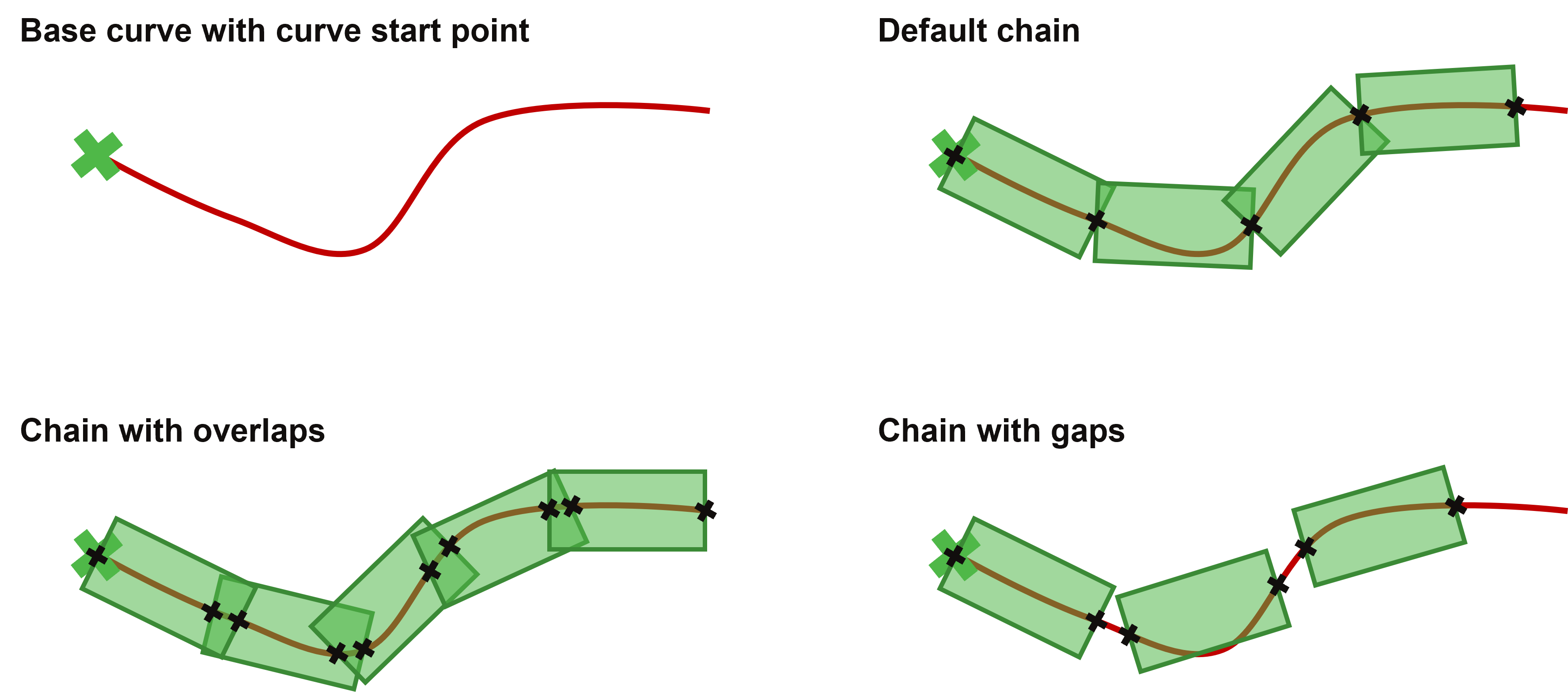
Fig. 2.10 Chain of patches beginning from curve starting point (with and without gaps / overlaps)
By default, the start point of the base curve is also the start point of the first patch in a chain. For structural laminates it is often required that the overlaps from neighboring chains are shifted against each other. This is usually done automatically by Artist Studio’s overlap optimization algorithm. In order to speed up the computation of the optimal overlap pattern, several chain positions are precalculated. The number of such chain start positions is by default set to ten, but it can be adjusted by the user. To simplify visualization the following example Fig. 2.11 shows 3 starting positions. This means, that between the start and the end point of the first patch (in its initial position), two additional starting points with three equidistant segments along the base curve are created. For each of these starting points a complete chain is precalculated.
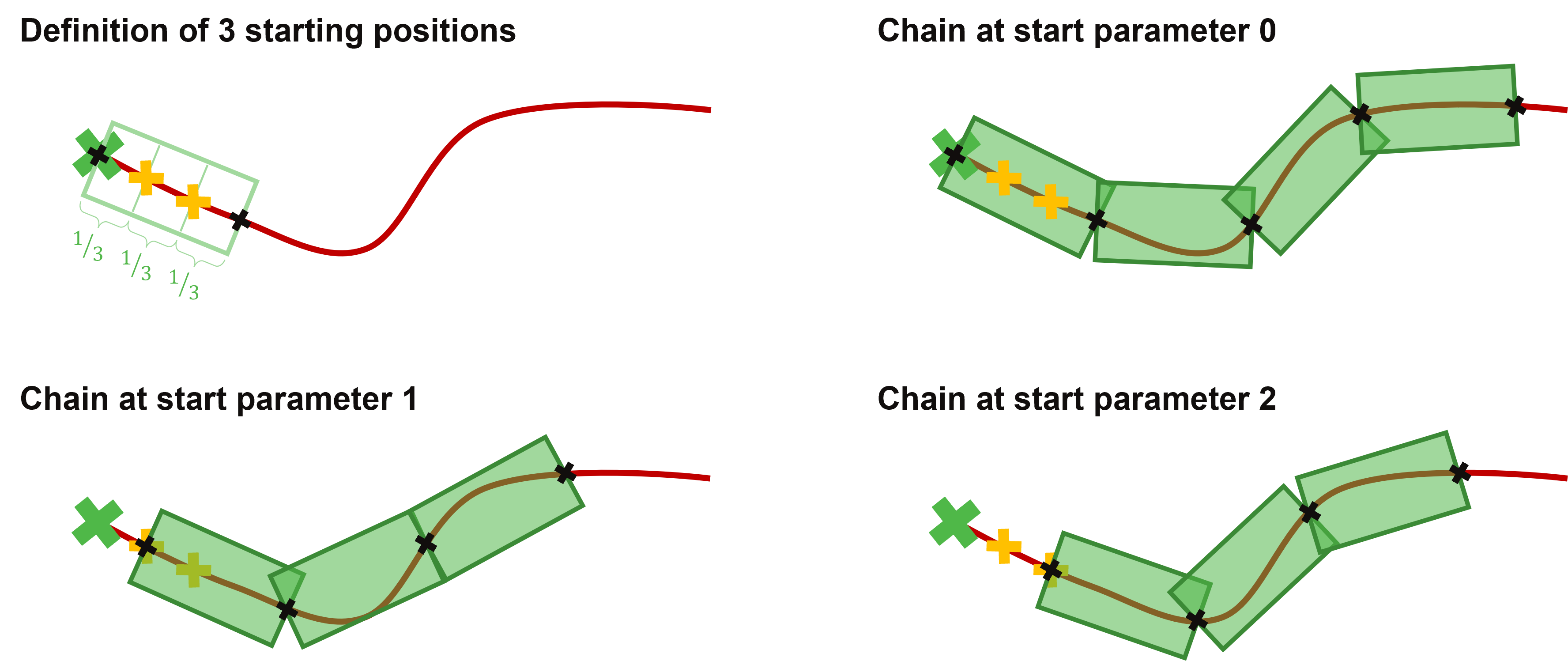
Fig. 2.11 All chain configurations for three starting positions
Chains interact with boundaries as well as with extrapolated curves. Patches whose start and end point lie completely outside a provided boundary or completely on an extrapolated curve segment will be automatically removed.
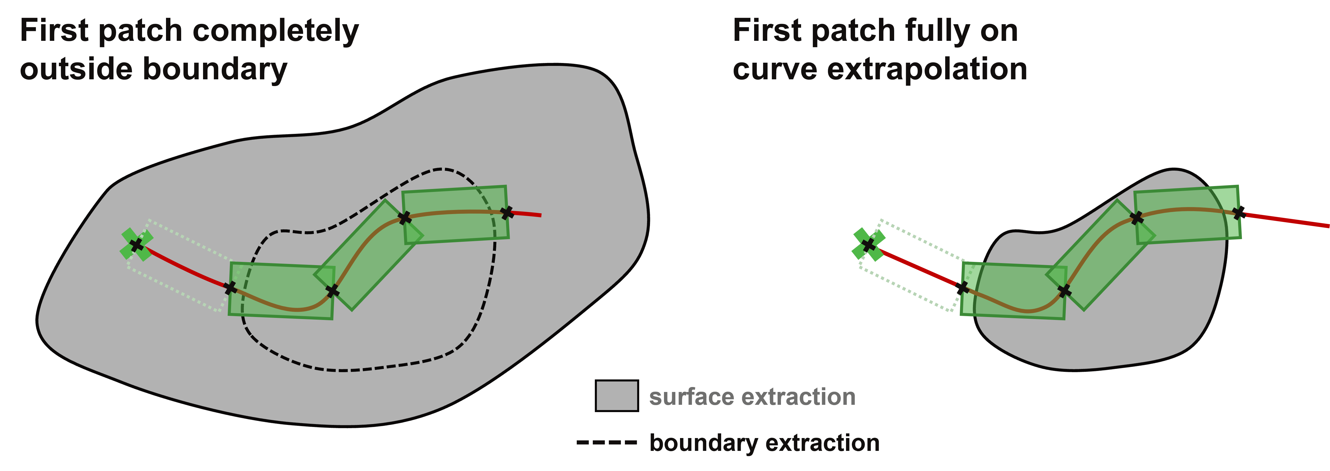
Fig. 2.12 Chain with removed patches outside boundary / on extraction