5. Getting started
5.1. Mouse controls
Artist Studio provides various types of mouse control modes for the user. The user can change the mode of mouse by following these steps:
step 1- Click on the
Viewbutton from the Menu bar.step 2- Select
Settings.step 3- Select the mouse control from the section
Mouse settingsdepending upon the choice.
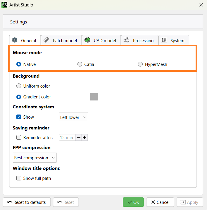
Fig. 5.1 Different mouse controls
Different mouse controls are as follows:
- Native:
Select: left click/drag
Additive Select: shift + left click/drag
Deselect: shift + right click/drag
Zooming: roll the wheel
Panning: ctrl + wheel pressed + drag the mouse
Rotating: ctrl + left click pressed + drag the mouse
- Catia:
Select: left click/drag
Additive Select: shift + left click/drag
Deselect: shift + right click/drag
Zooming: Keep rolling wheel pressed + click and release left or right click
Panning: Keep rolling wheel pressed + drag the mouse
Rotating: Keep rolling wheel pressed + left or right click pressed
- HyperMesh:
Select: left click/drag
Additive Select: shift + left click/drag
Deselect: shift + right click/drag
Zooming: ctrl + roll the wheel
Panning: ctrl + right click pressed + drag the mouse
Rotating: ctrl + left click pressed + drag the mouse
5.2. Change background color
Artist Studio provides two types of background: uniform and gradient. The user can either choose uniform or gradient color depending on the choice. Here are the steps to change the background color:
Step 1 - Click on the View button from the menu bar.
Step 2 - Select Settings from the context menu.
Step 3 - Select Uniform or Gradient color and to change the background color click on the corresponding boxes.

Step 4 - Choose the color you want to select as a background.
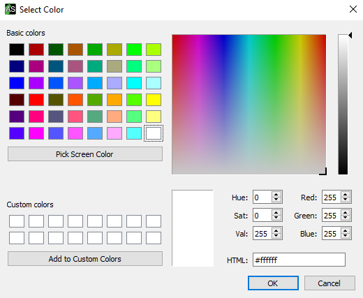
Fig. 5.2 Background color options in Artist Studio
5.3. Visibility and position of coordinate system
The coordinate system in Artist Studio specifies the position of any point in three-dimensional space by three Cartesian coordinates x, y,and z. One can change the visibility and position of the coordinate system as follows:
5.3.1. Visibility
Visibility of coordinate system can be activated or deactivated in Artist Studio. This can be done as follows:
Step 1 - Open the View menu.
Step 2 - Select Settings from the context menu.
Step 3 - Check or uncheck the Show button under Coordinate system for visibility.

Fig. 5.3 Visibility of coordinate system
5.3.2. Position
The position of Coordinate system in the viewport can be controlled. The user can place it at left lower, left upper, right lower or right upper depending on the choice. Follow these steps for changing the position of Coordinate system:
Step 1 - Open the View menu.
Step 2 - Select Settings from the context menu.
Step 3 - Select the suitable position from the drop-down menu as shown below:
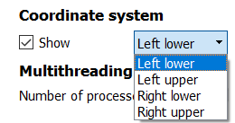
Fig. 5.4 Position of coordinate system
5.4. Define model style
Artist Studio enables the user to customize the look of their model. The user can choose different colors for faces, edges, patches, mesh, etc. of the model. This can be done as follows:
Step 1 - Open the View menu of the menu bar.
Step 2 - Select Settings.
Step 3 - Select either the Patch model or the CAD model tab.
Step 4 - Select color, style, and size depending on your requirements.
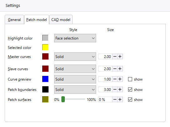
Fig. 5.5 Defining patch model style
When selecting the CAD Model tab other options are provided
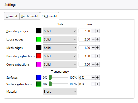
Fig. 5.6 Model style for CAD model
Note
For the two options Surfaces and Surface Extraction the Transparency will be chosen as a percentage
The last option Material allows to choose the material among a list
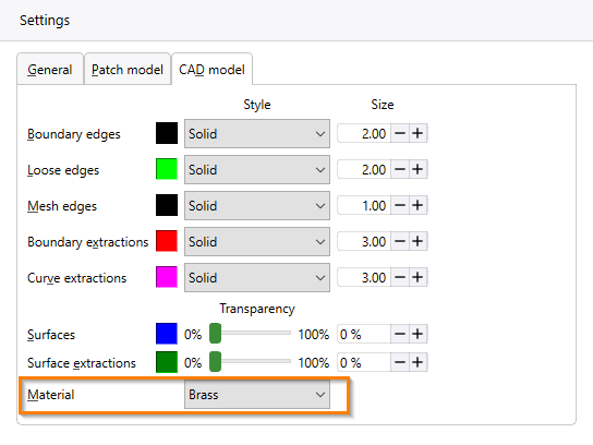
Fig. 5.7 Defining Material
Tip
All changes can be reset to default by selecting Reset to defaults.
5.5. File management
The fundamental methods of creating, importing, exporting, saving are explained below:
5.5.1. Create a new FPP model
To create a new FPP model click on New option from Quick access toolbar or from the File menu of the menu bar.
A new application window will open with a blank viewport.

Fig. 5.8 Creating a new FPP model from Quick access toolbar
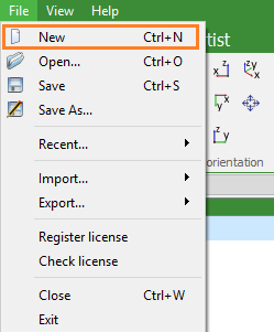
Fig. 5.9 Creating a new FPP model from File menu
5.5.2. Import the CAD model
Artist Studio enables the user to import any CAD model such as brep, stl, step or stp. To import a 3D model follow these steps:
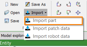
Step 1: Click on Import either from Quick access toolbar
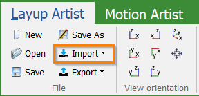
or from the File menu.
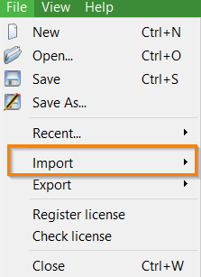
Step 2: Select Import part from the context menu.
Step 3: Browse the directory and select the model.
Step 4: Click on the Open button.
Geometry will be imported.
5.5.3. Export the CAD model
The user can export their geometries to remodel or reconstruct them further. To export a CAD model follow these steps:
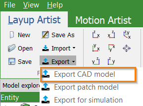
Step 1: Click on Export either from Quick access toolbar
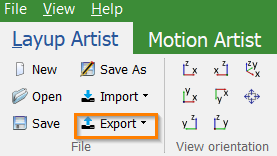
or from File menu.
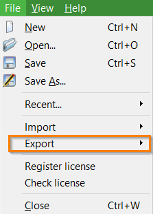
Step 2: Select Export CAD model from the context menu.
Step 3: Select a folder to export the model and enter a file name.
Step 4: Select Save as type such as brep, step or vrml etc.
Step 5: Finally, Click on the Save button.
Model will be saved with the entered name in the selected folder.
5.5.4. Open the FPP model
Let us see how to open a FPP model in Artist Studio:
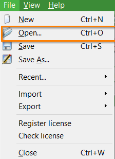
Step 1: Open the File menu and select the Open option from the context menu.
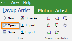
You can also select Open from the Quick access toolbar.
There is one more option Recent places, where you can see and open the recently opened FPP models.
Step 2: Clicking the Open option will open the browser dialog. Browse the directory and select one or more files you wish to open.
Step 3: Each selected file will open in a new application window.
5.5.5. Save new FPP model
Once you are done with the creation of your FPP model, you should save your model to avoid losing your work. Following are the steps to save the file:
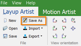
Step 1: From the File menu select Save As option
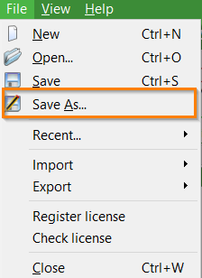
or select Save As option from the Quick access toolbar.
Step 2: Select a folder where you would like to save the FPP model, enter file name, which you want to give to your model, by default it will be saved in FPP format.
Step 3: Finally, click on the Save button and your model will be saved with the entered name in the selected folder.
5.5.5.1. Save new changes
After you make any changes, it is always useful to save your changes. If you want to save your model with the same name, then you can use either of the following simple options:
Just press
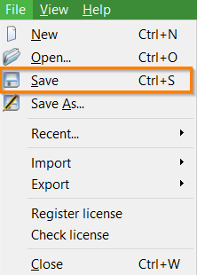
Ctrl + Skeys to save the changes.The user can also save the changes by clicking on the
Savebutton available at Quick access toolbar
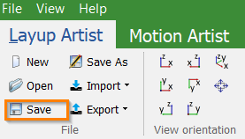
or in the File menu.
5.5.6. Import robot data
Robot movements can be imported from CSV files. This can be used to create machine data from placement positions that were calculated by an external software.
5.5.6.1. Robot data format
ARTIST STUDIO expects a ; separated file with a header at the first line of a CSV file that defines the format to use. The following formats are supported:
X;Y;Z;A;B;CPosition defined in X, Y, Z values and with rotation around Z axis (A), rotations around the derived Y axis (B), and rotation around the further derived X axis (C).
X;Y;Z;X;Y;ZPosition defined in X, Y, Z values. The second X, Y, Z values are the second position that defines the normal direction (from point 1 to point 2).
X;Y;Z;NORM_X;NORM_Y;NORM_ZPosition defined in X, Y, Z values. NORM_X, NORM_Y, and NORM_Z define the normal vector.
All consecutive lines will be interpreted as data with each line resulting in one patch.
Point data is always relative to the CAD root.
Note
CSV files need to be saved with either Windows \r\n or UNIX \n
line endings. Mac OSX \r line endings are not supported.
5.5.6.2. Importing robot data file
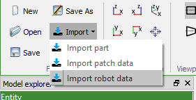
To import the CSV data files, click on Import robot data in the Ribbon bar:
In order to be able to successfully import robot data, the following prerequisites have to be fulfilled:
At least one machine config defined
Robot cell loaded
After choosing the file to open, you will be prompted to first select the machine config to use when importing the data:
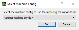
Not selecting a machine config or pressing cancel will abort the import process.
After choosing the machine config, you will be prompted to select the base system to use as reference system for the machine data coordinates. By default, the world zero position will be used.
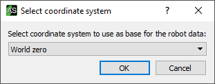
Note
Base systems have to be imported with your CAD models or defined manually.
The X;Y;Z;X;Y;Z and X;Y;Z;NORM_X;NORM_Y;NORM_Z formats only define a
normal direction but are missing further information to fully define each point
as a coordinate with position and rotation. Therefore, you will be prompted to
define another vector to fully define positions:

It’s possible to either choose one of the unit vectors by entering x, y, or z,
or manually enter the directional vector as a ; separated list, e.g. -1.0;0.0;0.0.
The chosen vector should correspond with the main direction of the patch,
i.e. the direction of the long edge.
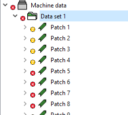
Afterwards, a data set with patches based on the position data will be generated.
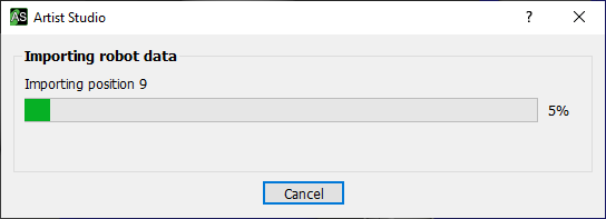
At the end of the process, a new data set with patches will have been created.
Note
The current implementation does not support adding a heating position for prepreg production. This will have to be added manually.