10. Robot movements
10.1. Robotic cell information
Information about a robotic cell and production system is made up of three elements:
CAD of cell elements
Position of elements in a cell (robot settings)
Information about fixed robot positions taught by a robot programmer (machine configs)
Warning
Make sure to select correct (matching) machine config and cell.
10.1.1. CAD of cell elements
A robotic cell is built of fixed elements (robots, cabinets, safety fences etc.). Shapes
of all elements of one cell are stored in one rcd file. Standard cells (SAMBA Pro, SAMBA Step
and SAMBA Step L with two gripper sizes) are installed in the rob subfolder in the
Artist Studio installation folder. To use other cells, see Custom cells.
Before generating a data set, one of these cells has to be chosen. See Select manufacturing cell.
10.1.2. Positions of elements in a cell
Final positions of elements of a cell should be measured and updated in Artist Studio, see Robot settings section below.
To display all movements and prevent collisions in movements towards the approach or from the leaving positions, the exact taught positions have to be provided to Artist Studio. Loaded defaults can be modified manually, see Machine configurations.
10.2. Robot settings
For every geometry, you will be provided with the robot settings. However, if you want to change settings then click on Robot settings under the Miscellaneous group.
Robot settings are divided into five groups depending on the various robot parts which are:
10.2.1. Positioner

Position Change here the position of Positioner by changing the value of x, y, z and its corresponding yaw, pitch and roll values.
Joints
Here, you can hide or unhide the various parts of Positioner robot by simply clicking or unclicking the green eye  button.
Mount plate - Offset vector The position of Mount plate is adjustable. You may want to change the position of Mount plate depending on the complexity of your geometry. This option allows you to make changes in the default position of Mount point.
10.2.2. Picker

Position:
Change here the position of Picker by changing the value of x, y, z and its corresponding yaw, pitch and roll values.
Joints:
Here, you can hide or show the various parts of Picker by simply clicking eye  icon.
icon.
Picker tool:
The picker tool, commonly referred to as Gripper, is attached to the end of the picker robot. It typically consists of a foam element (pictured black) and other elements of the gripper assembly like the quick change system. For some machines, the currently active gripper can be selected using the dropdown.
It is also possible to modify the visibility of the Gripper by clicking on the eye  icon next to the dropdown.
Note
After selecting a different gripper from the dropdown, the gripper visualization in Motion Artist will only update after
closing the Robot settings or by clicking on the eye  icon.
icon.
Tool offset vector:
The tool offset vector is typically a machine-specific and constant value. A change should only be needed in rare occasions and should be double-checked with Cevotec Support.
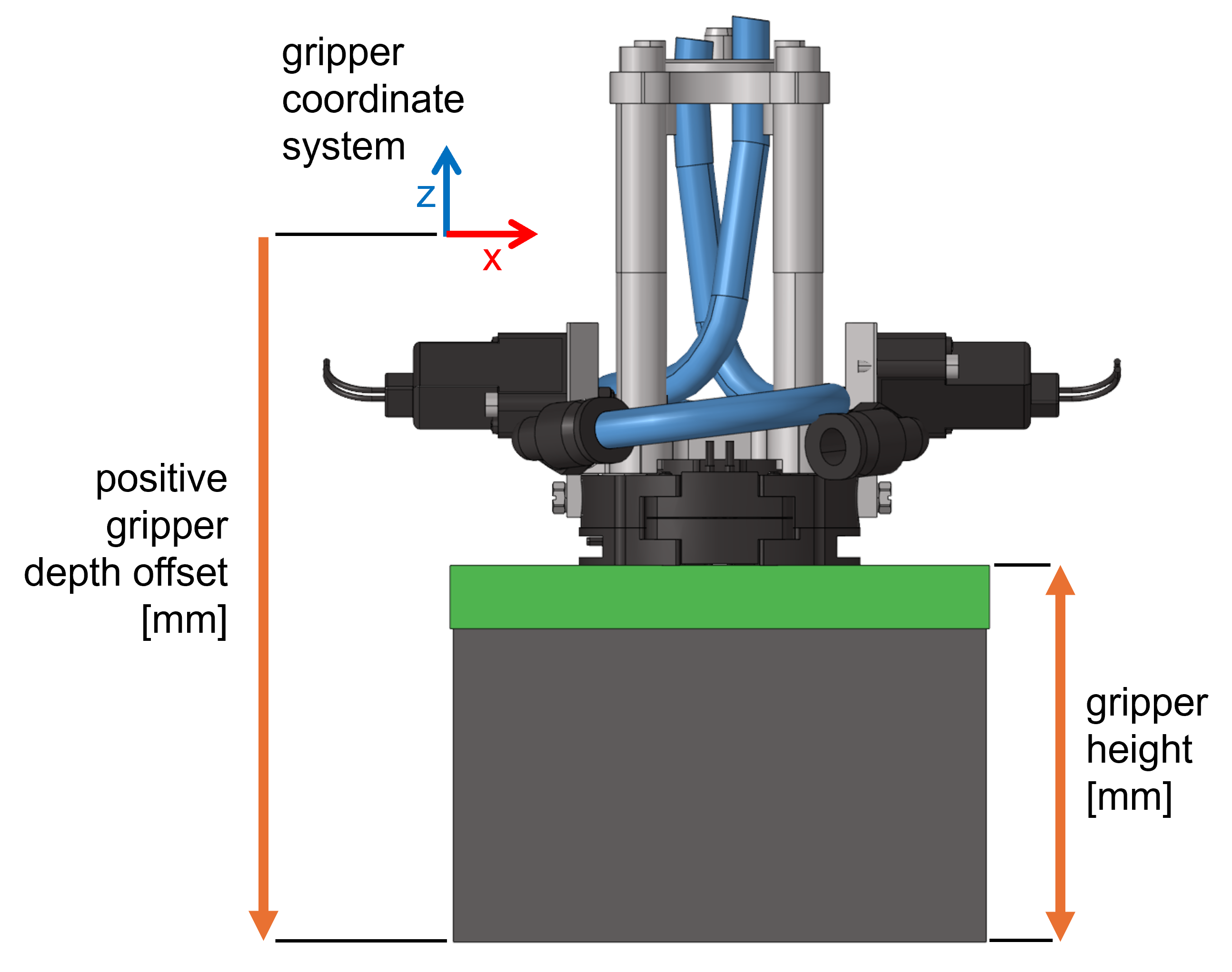
Gripper Height & Depth Offset:
Gripper Height and Depth Offset depend on the currently used gripper. If the gripper is selected from the dropdown, these values will automatically be set based on factory settings for the specific gripper type.
In some occasions, it might be necessary to modify these values, e.g. when using a non-standard gripper. The height of the gripper is measured in mm from the bottom of the gripper foam to the top of the base plate, not taking any attachments (such as flanges) into account. The depth offset is the distance in mm along the negative z-axis of the gripper coordinate system from the gripper CAD system origin to the bottom of the gripper. I.e., this value is positive when the z-axis is pointing up. Please see also the figure below.
Note
The gripper height is currently only used for delta kinematic picker robots. In all other cases, this value is purely informative (e.g., as additional information for the machine operator).
10.2.3. Frame

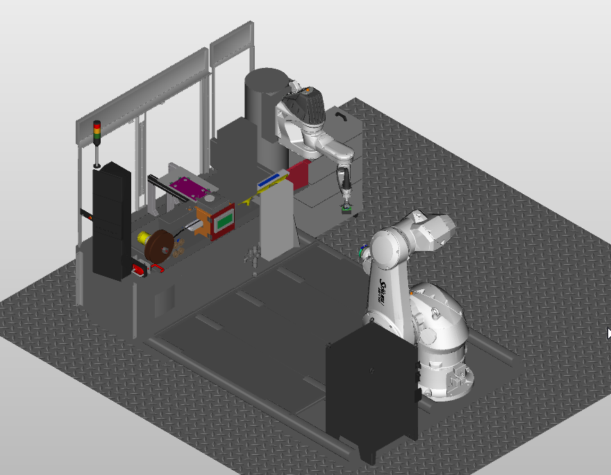
The manufacturing cell is enclosed in a frame to give a safe environment of work. However, you can change or hide different parts of the frame for the simulation.

Position: Change here the position of Frame by changing the value of x, y, z and its corresponding yaw, pitch and roll values.
Elements:
Here, you can hide or unhide various parts of Frame by simply clicking or unclicking the green eye  button.
You can see here the frame after hiding some parts which can be done for better visibility purpose.
10.2.4. Feeder
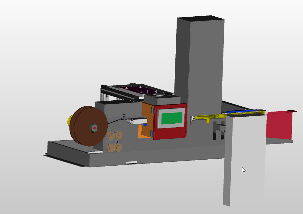
Feeder is a box like structure which feeds the manufacturing cell with tape for patching on the geometry.
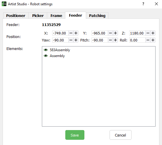
Position: Change here the position of Feeder by changing the value of x, y, z, and its corresponding yaw, pitch and roll value.
Elements:
Here, you can hide or unhide various parts of the Feeder by simply clicking or unclicking the green eye  button.
10.2.5. Patching
In Motion Artist for simulation of the manufacturing cell, the first requirement is to set Deposit Frame where the interaction of robots - Picker and Positioner will occur.
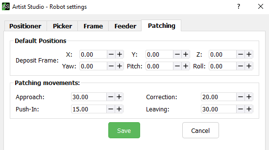
Default Position: Deposit frame Change here the default position of Deposit frame by changing the value of x, y, z and its corresponding yaw, pitch and roll values.
Patching Movements:
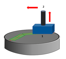
There are basically four patching movements of Picker while placing a patch on the surface of the geometry. Here, the user can define the default values for these movements which are:
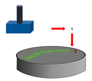
Approach height - It is a two step patching process. The picker axes will stop at position 1 before patching at surface 2. This is to avoid any collision and correct placement of patches on the CAD surface.
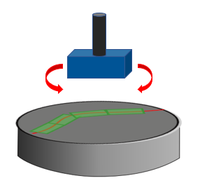
Correction height - This will correct the position of the gripper for proper alignment of patches on the CAD surface.
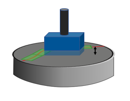
Push-in depth - It defines the depth with which the gripper will Push-in onto the CAD surface in the Target position.
Leaving height - This movement is same as Approach but after successful placement of the patches. Here, the picker will stop at position 2 after placing the patches on the surface 1.
10.3. Calibrate robot
Industrial robots are repeatable but with time their accuracy decreases. The accuracy of industrial robots can be improved by calibration. Calibration tools are required to calibrate the robots. To calibrate robots follow these steps:
Attach the calibration tools to Positioner axis 6 and Picker axis 4.
Choose one point in space and manually move both Positioner and Picker robot towards that point and try to fit attached calibration tools into each other.
When the both calibration tools fits into each other then note down the values of Positioner joints and Picker world coordinates from the display panel.
To calibrate the robots in Motion Artist, click on
Calibrate robotfrom theMiscellaneousgroup.Robot calibrationwindow will appear.

Enter the values for Positioner joints and Picker world coordinates noted above to create a calibration point and click on the
Addbutton to add that point for calibration.It is recommended to atleast take three different points in space and check for fitness of calibration tools into each other. For every different point in space, add its calibration point in
Calibrate robotwindow.After adding all the calibration points click on
Run calibration.
This will calibrate both Positioner and Picker axis.