12. Integration with FEA
Fiber Patch Placement is all about high performance laminates. In order to verify a laminate design it is common practice to perform a finite element simulation. However, FPP laminates usually consist of several thousands of patches. It is not feasible to manually model such complex laminates. This is where the Artist Studio FEA tools come into play to automatically setup your simulation model.
12.1. Supported formats
Depending on your selected format, not all solver features are supported. Please check the list below for an overview.
Solver |
Modelling method |
Element types |
OptiStruct |
PCOMPP, PCOMPG, PCOMP |
CTRIA3, CQUAD4 |
Nastran |
PCOMPG, PCOMP |
CTRIA3, CQUAD4 |
ANSYS |
ComposicaD 2D |
SHELL181 |
Note
The elemental material orientation can be defined by an angle relative to the elemental coordinate system or by a reference to an external coordinate system. Note that when using coordinate systems references, the FEA model export supports only systems of type CORD2R or CORD3R.
Note
The element size of the finite element mesh and the draping settings for the patch in Patch Artist can have a profound impact on the results of the mapping process. On surfaces with high curvature, deviations may occur, resulting in elements being incorrectly associated with a patch. Please carefully check the modeling results and refine your mesh (FE and/or draping) if needed.
12.2. FEA model export
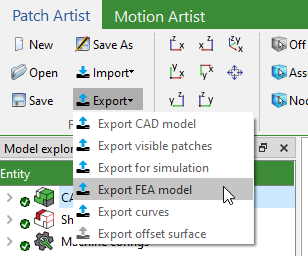
The FEA model export dialog can be accessed via Export > Export FEA model.
12.2.1. Prerequisites
Ideally start in your preprocessor with an empty project. Load the base geometry of your part and perform the meshing.
It is not recommended to use the default material coordinate system, which is the element coordinate system (specified by the orientation of the vector from first to second node of the element). Instead you may choose to apply a custom material coordinate system. This will reduce the number of properties produced and facilitates result interpretation.
Finally, export the solver deck in standard format.
Note
Please ensure that the location of your mesh within the global coordinate system matches exactly the one of your CAD geometry in Artist Studio.
12.2.2. Settings
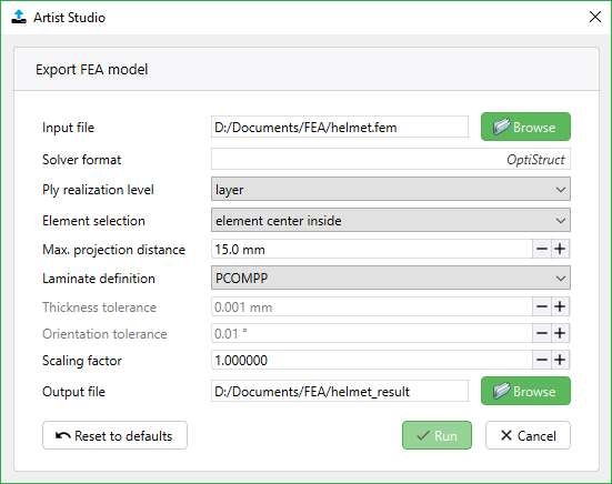
The entries in the Export FEA model dialog are:
Input file - Location of the solver input deck that is supposed to be extended with FPP model data
Solver format - The solver format will be automatically identified based on the input file
Ply realization level - Selection of the laminate entity level that is used to create plies
e.g., when sublayer is selected, all patches inside a sublayer will be merged to form a single ply
overlaps will be taken correctly into account in terms of increased thickness and averaged fiber orientation
Element selection - Specifies when an element is considered to be inside the patch boundary and will therefore be added to the ply
element center inside: the center of the element is inside; ply element selection will usually be slightly larger than actual patch size
all nodes inside: all nodes of the element are inside; ply element selection will usually be slightly smaller than actual patch size
element center inside bounding box: a faster but less accurate version of
element center insidethat uses bounding boxes of the patches instead of projections; not suitable for curved surfaces or non-rectangular patchesall nodes inside dounding box: a faster but less accurate version of
all nodes insidethat uses bounding boxes of the patches instead of projections; not suitable for curved surfaces or non-rectangular patches
Max. projection distance - The maximum allowed distance between a node or the center point of an element and its projection onto the laminate mesh. Higher values will slow down model creation but might be necessary when using FE meshes that deviate from the selected Patch Artist surface or when using the Patch Artist thickness offset feature. Please check the model export results carefully. This setting is used only in
element center insideandall nodes insideLaminate definition - Property definition (available options depend on selected solver format); zone based approaches identify areas with same layup according to tolerances specfied further below
PCOMPP: Ply base modelling approach - ply definition doesn’t require zones
PCOMPG: Zone based modelling approach - plies are connected via global ply id
PCOMP: Zone based modelling approach - plies are not connected
Thickness tolerance - Reduction of created PCOMP/PCOMPG properties by identifiying zones with the same layup, with ply thickness deviation less than this value
Orientation tolerance - Reduction of created PCOMP/PCOMPG properties by identifiying zones with the same layup, with local ply orientation deviation less than this value
Scaling factor - Scaling factor for the conversion of the solver deck length system to the Artist Studio internal system in millimeters
Output file - Location of the result file
12.3. HyperMesh Plugin
Cevotec implemented its plugin in HyperMesh because it is a generic preprocessor, i.e. it supports a large number of different FE-solvers. The plugin is installed automatically if an instance of HyperMesh is found on your computer during the installation of Artist Studio. Have a look at chapter 3.2 Installation of Artist Studio for more details on the installation process.
12.3.1. First steps
If the plugin is successfully installed you should be able to see an Artist Studio entry on the far right of the HyperMesh menu bar. The drop-down menu has the following entries:
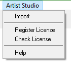
Register License and Check License have the exact same functionality as in Artist Studio. Go to chapter 3.2 Register License if you need a recap on how to register your license.
The Help button opens the help browser with the documentation.
12.3.2. Laminate import
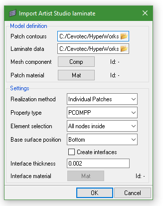
An import dialog opens if you click on the Import entry in the Artist Studio menu.
12.3.2.1. Prerequisites
Naturally, before you can import a laminate in HyperMesh, you have to export it from Artist Studio.
In order to do this, open your *.fpp file in Artist Studio and identify which patches are visible, hidden and suppressed.
Then go to the File group and click on Export > Export patches.
Adjust the Patch export settings as needed, making sure that Simulation data is enabled.
The export creates two files: one *.step file with all the patch geometries and a *_simulation.csv file with the meta data.
Ideally you start in HyperMesh with an empty project.
Load the base geometry of your part and mesh it.
If you are unsure which file to use just open your *.fpp file and go to File group > Export > Export CAD model.
Next, create your patch material in HyperMesh.
That’s it for the preparatory work.
12.3.2.2. Model definition
In order for the laminate creation algorithm to run, all information must be provided in the Model definition group box.
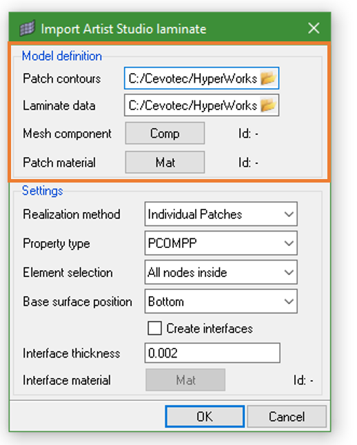
The entries for the model definition are:
Patch countours - select the *.step file that was created when you exported your laminate for simulation in Artist Studio
Laminate data - select the *.csv file that was created when you exported your laminate for simulation in Artist Studio
Mesh component - click on the
Compbutton to select the HyperMesh components with the mesh on which the laminate will be generatedPatch material - click on the
Matbutton to select the material that will be assigned to the patches
After you’ve specified the necessary input for model creation you can click on OK to create your laminate. Depending on the number of patches in the laminate and the machine you’re using this may take some time.
12.3.2.3. Settings
+In the previous section we dealt with the bare minimum of input information that is necessary to create a laminate. However, the way the laminate is created can be influenced using the entries in the Settings group of the dialog.
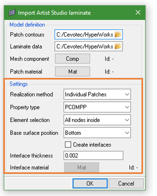
The functionality of each of the dialog’s entries are as follows:
Realization method - select Individual patches if a ply should be created for every patch. If you prefer a smeared approach that combines all patches of a sublayer into a single ply select Sublayer. The latter method averages the fiber orientation in areas of overlapping patches and adjusts the thickness accordingly.
Property type - select the property type that you want to use for the laminate. Depending on the selected solver profile different options are available
Element selection - defines the element selection behavior (i.e. which elements belong to a patch and which do not). If All nodes inside is selected all the nodes of an element have to be inside the boundary of the patch. If Element centroid is selected this has to be true only for the center of the element.
Base surface position - define the position of the laminate relative to the surface. Available options are: Bottom, Center, Top
Create interfaces - check this box if you want to create pure matrix interface layers between patches
Interface thickness - the thickness of the matrix interface layers
Interface material - specify the material for the interface layers by clicking on the
Matbutton