7. FPP laminate design
7.1. Visualization of curve geometry
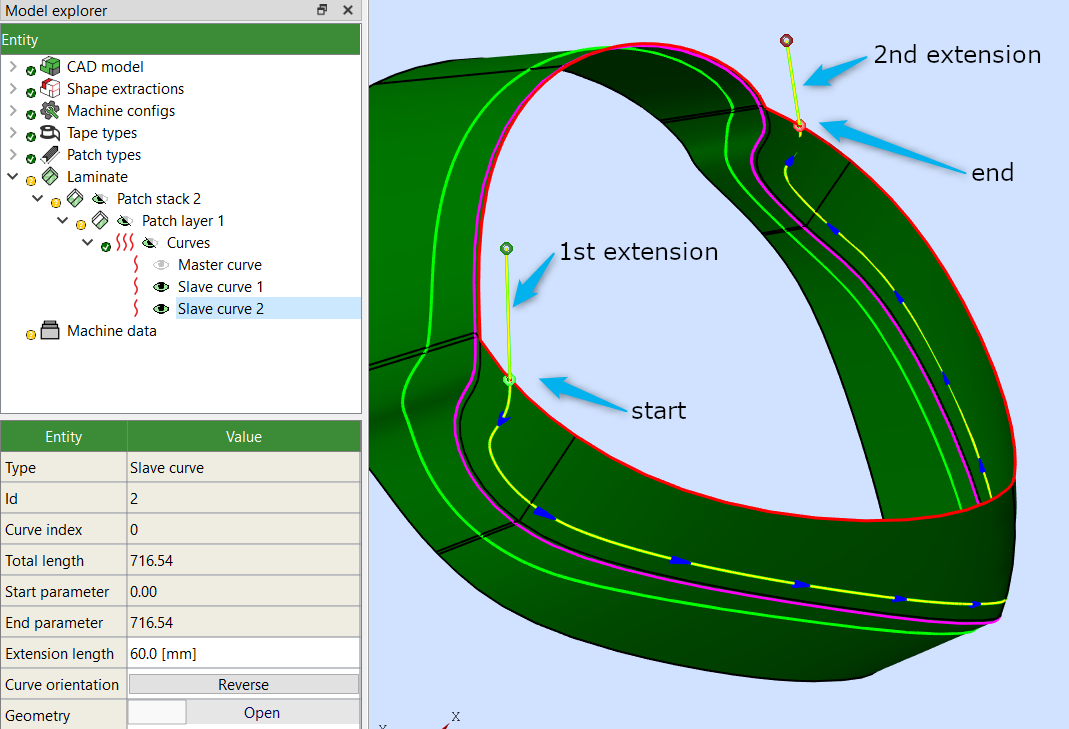
If you select “Show orientation” on the ribbon, and select one or more curves, start/end points of the curve and the extensions are visualized.
For open curves there are two linear extensions, at the beginning and at the end. Patch placement will start at the start point of the first extension, marked with a dark-green bullet. The start point of the curve is marked with a light-green bullet. Then blue or red arrows indicate curve direction. The end point of the curve itself is marked with a light-red bullet, and the end point of the end extension with a dark-red bullet:
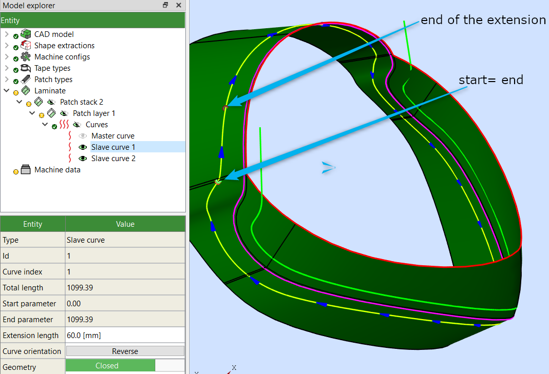
Closed curves are curves with the start and end points at the same location. There is no extension before the start point of the curve, and extension behind the end of the curve is not linear but follows curve’s shape. Patch placement will start at the start point of the curve, marked with a light-green bullet. Then blue or red arrows indicate curve direction. The end point of the curve itself is marked with a light-red bullet, and the end point of the end extension with a dark-red bullet:
The part of the curve between the light-green start and dark-red end of extension may be covered by patches twice. The flow could be schematically visualized in the following way:
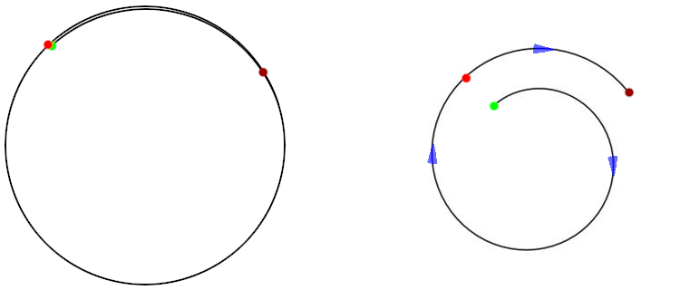
The right spiral image shows only the order in which patches are initially generated, starting from the light-green start point, and then following the curve and the extension. Note however that all patches within one layer are considered to be at the same position (height/depth) and to be interchangeable. For example, when later generating machine data for robots, patches originally coming from extension (between light and dark red bullets) might be placed before (i.e., deeper than) the patches originally created in Patch Artist based on the main part of the curve.
7.2. Visualization of laminate properties and quality review
Several color plots are available for visualization of laminate parameters and quality metrics. They are accessible via the Quality review group of the ribbon bar. The following metrics are supported:
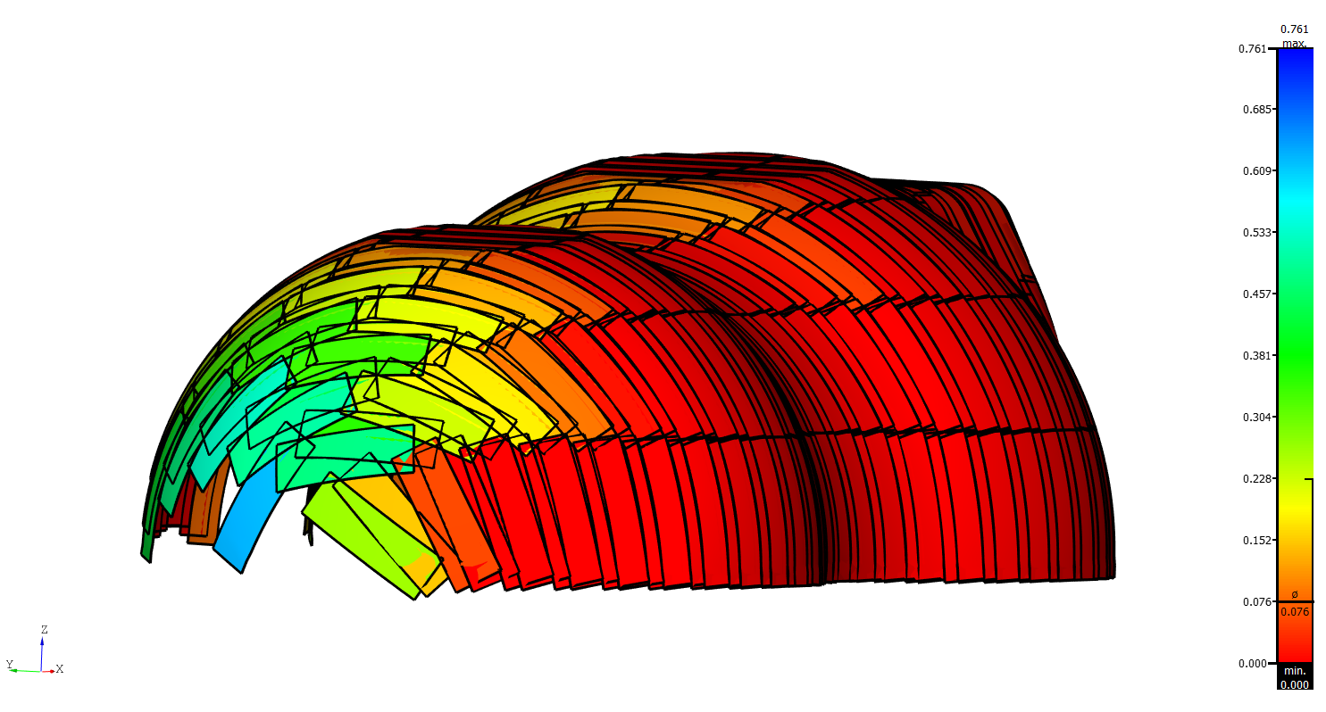
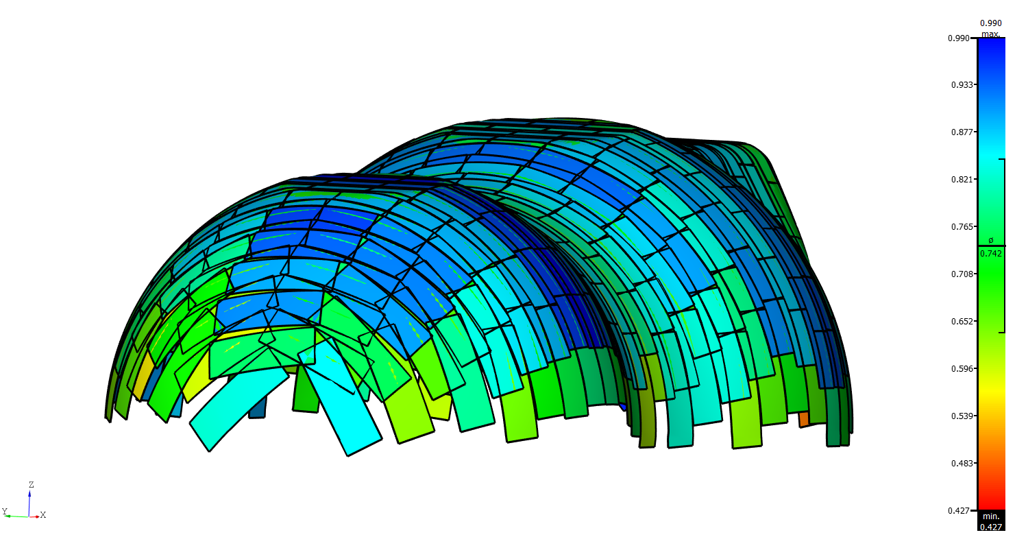
- Patch overlap quality
Quality of patch overlap between different (sub-)layers. Patches of neighboring (sub-)layers should overlap as much as possible to increase structural integrity of the laminate. The plot color-codes overlap of each individual patch with the neighboring patches in different (sub-)layers. The color scale on the right shows minimum and maximum as well as mean overlap quality of the laminate. Use layup optimization to improve layup quality. Note that this quality metric is only sensible for laminates with multiple (sub-)layers.
The figure below shows overlaps of an example laminate before and after overlap optimization. Mean overlap of the laminate increases strongly with optimization. The breaking points of the laminate caused by coinciding patch ends disappear.
- Patch length
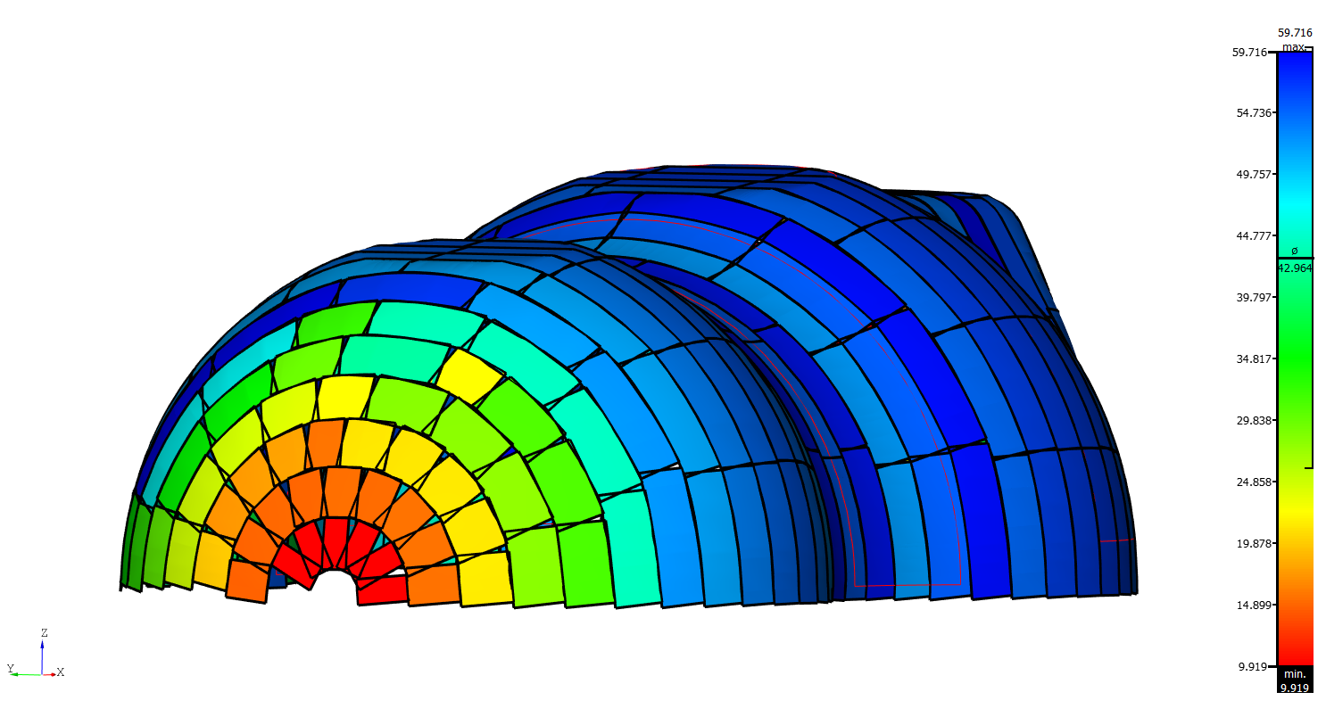
Color-code patches by their length. Minimum and maximum length of patches in the laminate as well as mean length are shown in the color scale on the right. Use this plotting mode to visualize length distribution when patching with variable length.
An example laminate using variable length is shown in the figure below.
- Thickness distribution
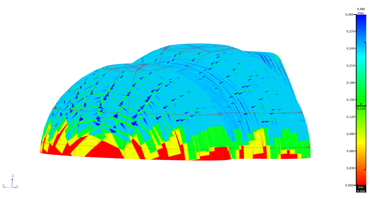
Shows the laminate thickness. Thickness depends on the number of patches overlapping at any given point as well as tape thickness. The scale on the right shows minimum and maximum as well as mean thickness of the laminate. Use this tool to see overall thickness of your laminate design as well as variations within the laminate. In contrast to other metrics the color plot does not apply on a patch-by-patch basis but as a single rendering on the surface.
The figure below shows thickness distribution for a laminate with three sublayers.
Warning
Please make sure that the normals of the faces of your part surface and the patch normals are aligned in the same orientation. If there’s a mismatch, some of the patches might be visualized inside out, as shown in the following screenshot. To resolve this issue, adjust the face normals and reload the file. If necessary also recreate the patches.
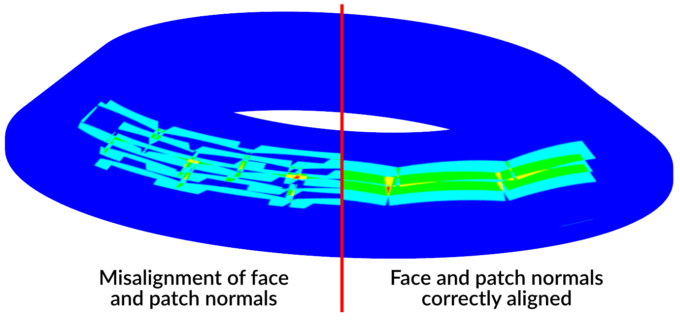
Fig. 7.1 Example of misaligned patch and face normals when plotting the thickness distribution
7.3. Manually adjusting positions of patches
It’s sometimes necessary to fine tune your FPP layup. For this purpose you are able to freely move and rotate individual patches on the surface.
Right-click on a patch (or select a group of patches and right-click on one of them) and select
Move or modify patch from the pop-up menu. This shows the move-patch dialog and a preview of the patch position (red grid)
with a corresponding coordinate system.
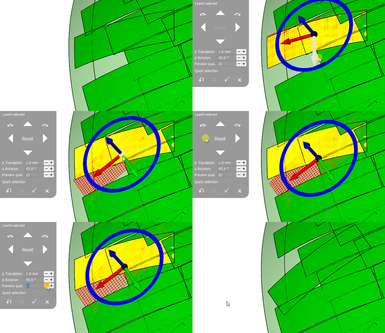
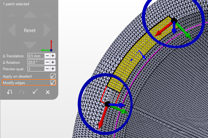
You can move the patch by dragging the red (parallel to the patch orientation) or green (perpendicular to the patch orientation) arrows, or rotate it by dragging the blue circle around the coordinate system. To freely translate the patch, drag the black sphere at the center of the system.
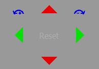
Alternatively, you can use the arrows of the dialog for the same purpose. In the image below we highlighted the arrows of the dialog with the colors corresponding to system handles. With Reset you can resets the position of the patch to its initial state (the one before opening the dialog).
You can adjust the following settings to your needs.
Table 7.1 Pach movement settings Δ Translation
Translation increment for a single step (used only for the dialog buttons)
Δ Rotation
Rotation increment for a single step (used only for the dialog buttons)
Preview qual.
The quality of the preview draping mesh. A lower quality will speed up your preview. The final patch shape is not affected by this setting.
Apply on deselect
If checked, any repositioning of a patch will immediately be applied after the patch is deselected. This way modifications to multiple patches can be applied in quick succesion. But be careful not to introduce any unwanted modifications.
Modify edges
While checked, switches to the mode for interactively modifying patch edges.
Tip
Use the dialog to perform precise movements and the interactive handles when aligning patches relative to other entities.
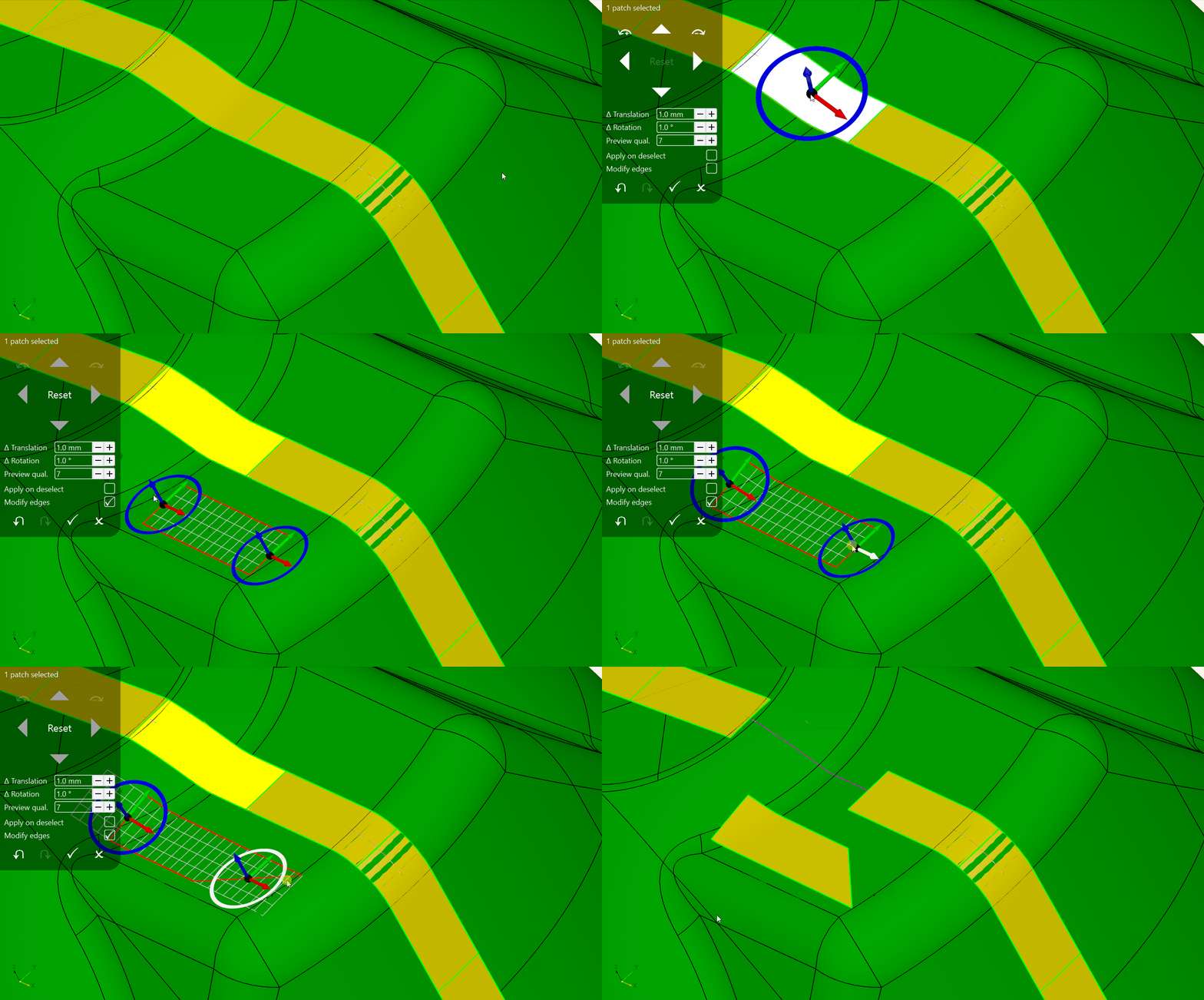
When manually fine tuning your laminate, you may also want to change the shape of a specific patch. You can do this by entering the Modify edges mode of the patch movement tool. This allows you to interactively move the front or back edge of a patch, effectively changing its length. Additionally, when using the feature for trapezoid patches (see Developer settings and beta features), you can also rotate the edges, changing the angles of the trapezoid patch.
Note
Modifying patch edges results in the generation of a new patch type. It is generally better to avoid using too many different patch types to reduce scrap rate.
Note
Unlike patch movement, modifying the edges cannot apply to multiple patches at the same time.
7.4. Adjusting patch shape for specific patches
When creating a layer using a fixed-length patch type, all patches in that layer will initially have the same shape, as defined by the selected patch type.
However, if only specific patches require a different shape - such as a different length or, for trapezoidal patches, modified front or back angles - you can override the default patch type per patch. There are two ways to do this:
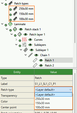
Selecting a patch-type override
First, create a patch type with the desired shape. Then, select the patch you want to modify, and use the patch type combo box to assign the new patch type to it.
Manual adjustment via ``Move or modify patch``
Open the
Move or modify patchdialog and check theModify edgescheckbox.Instead of a single arrow set for moving the patch center, you will now see two arrow sets - one for the front edge and one for the back edge.
You can drag the red arrows to change patch length.
If trapezoids are enabled, the blue circles additionally allow adjusting the front and back angles.
A red outline will preview the resulting patch shape. The patch width remains fixed, as determined by the tape width.
Once you confirm the changes (by accepting the dialog, or by selecting another patch while
Apply on deselectis checked), a new patch type is created automatically and assigned as an override, only to the modified patch.
Note
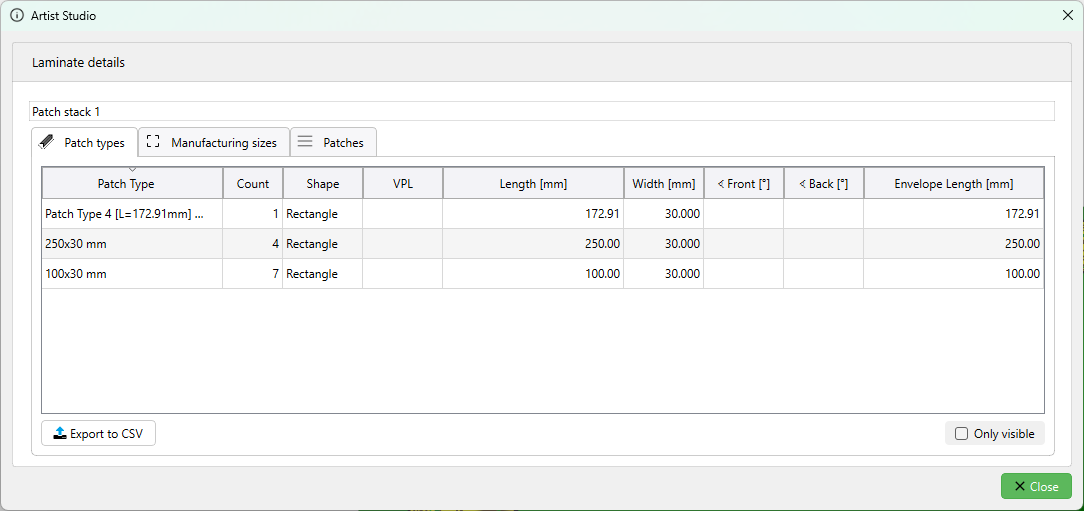
If you created a layer containing patches of different sizes, you can get a quick overview of how many distinct
patch types (or shapes, regardless of tape type) are present at a specific laminate level. To do this, right-click
on the stack, layer, sublayer, or similar element and select Details to open the statistics popup.
Note that suppressed patches are excluded from these statistics. You can choose whether to summarize data for the entire laminate level or only for the currently visible portion. The same statistics popup is also available when working with data sets in Motion Artist.
7.5. Automatic variable patch length
When defining Patch types, you can choose between patches of constant or variable length. Selecting
either of the variable options - continuous or discrete - enables the patch length to vary from one
patch to the next, and allows it to be automatically adjusted during patch creation.
This section outlines the use cases and criteria for automatic patch length determination when using variable-length patches. There are two main benefits:
Minimize scrap material
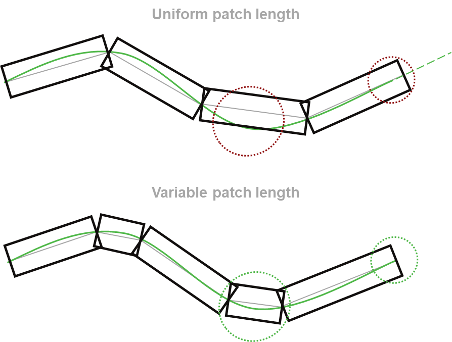
Patch lengths are automatically chosen to minimize the gaps at the start and end of each guide curve. This reduces the need for artificial curve extensions (common with constant patch length) and lowers material waste by minimizing boundary overlaps.
A similar effect can also be achieved manually, by assigning custom patch types at the ends of a chain, or by using the Move or modify tools in the GUI.
Follow curves closely
Shorter patches are used in areas where the curvature of the guide curve on the surface is high. This reduces angular deviation between patches and the curve, improving the structural properties of the laminate - especially when guide curves follow load paths.
7.5.1. Adjust patch length to fit chain
In this section, we compare the outcomes when using constant-length patches versus variable patch lengths (VPL). The illustrations below demonstrate the differences:
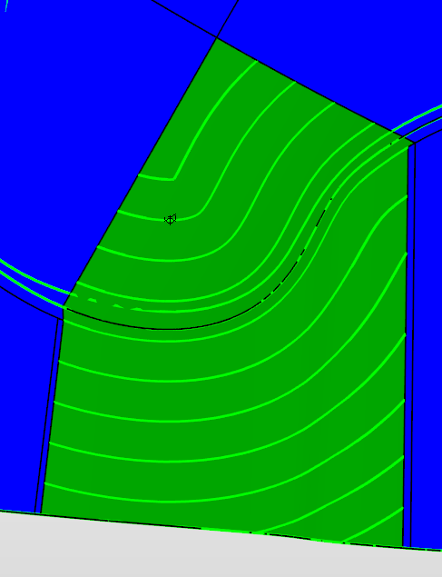
7.5.1.1. Constant-Length Patches
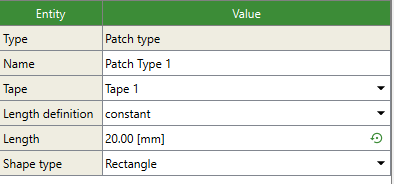
Constant-Length Patch Definition:
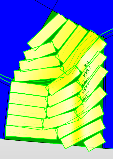
Resulting Laminate with Constant-Length Patches:
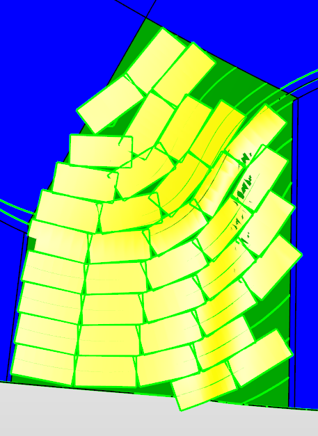
As observed, constant-length patches result in significant gaps at the surface edges and suboptimal alignment with the guide curves.
7.5.1.2. Variable-Length Patches
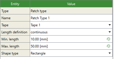
Variable-Length Patch Definition:
Resulting Laminate with Variable-Length Patches:
With variable-length patches, the laminate exhibits minimal gaps, ensuring a more efficient surface coverage. This is achieved by adjusting the patch length per chain in a way to minimize these gaps. This approach can however still lead to large deviations from the guide curves.
7.5.2. Follow curves closely
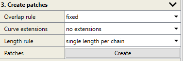
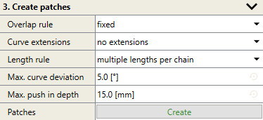
This section discusses how to enable the second option for variable patch lengths, which allows for better adherence to guide curves. To enable this feature, you will need to edit the keys.xml file (Variable patch length: multiple lengths per chain (beta)). After modifying the XML file, go to the layer settings and alter the “Length rule” as follows:
Default Length Rule Setting:
Modified Length Rule Setting:
Resulting Laminate with Enhanced Curve Following:
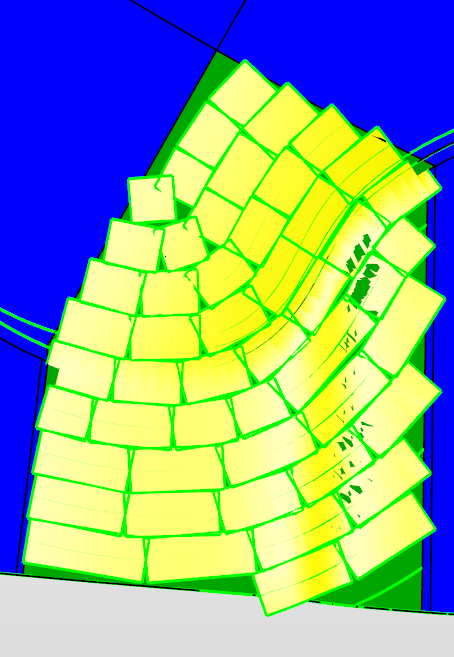
As demonstrated, this feature enables the patch centerlines to more closely conform to the guide curves, thus improving laminate properties.
The behaviour of patching with variable length is controlled by a variety of settings you can configure in Patch Artist. Here, the impact they have on the resulting laminate are described briefly. For a precise description of individual settings see the referenced sections.
The settings described under Patch types allow setting the range of allowed patch lengths for creating the laminate. These should be set within the capabilities of the used machine and control the overall length of employed patches. Furthermore, the range between minimum and maximum patch length has an impact on the resulting laminate. A large range (minimum patch length significantly smaller than maximum length) provides flexibility and minimizes the length of the curve extensions required to achieve a full laminate. A small range requires longer curve extensions as one starts to approach the case of constant patch length.
Additionally, when creating the patches as described by Create patches, you can set Max. curve deviation and
Max. push-in depth. Patches with variable length are created in such a way, that the angular deviation of the center line of
a patch from the guide curve is below the angle set by Max. curve deviation. Patches should also not require the gripper
to push in by more than Max. push-in depth.
These two parameters allow adjusting the laminate in different ways. Lowering Max. curve deviation means that the guide curve
is followed more closely and patches become shorter to follow the curvature of the curve on the surface. Adjust this value to
closely follow load paths and reduce gaps between patches of neighboring curves.
In contrast, lowering Max. push-in depth will lead to shorter patches where the curvature of the surface itself is high. Adjust
this value based on gripper limitations.
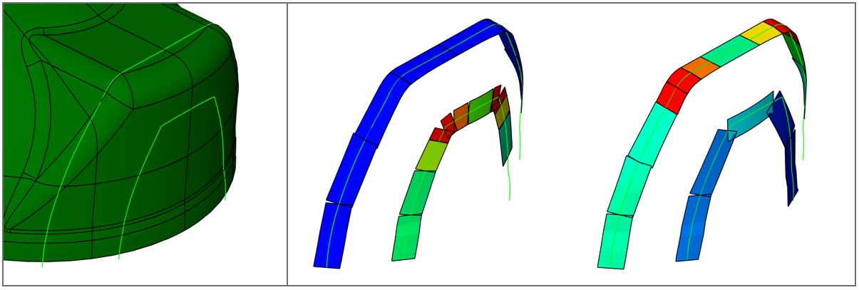
The illustration below demonstrates the effect of the two parameters on a laminate consisting of two curves. Patch lengths are
color-coded. The curves and the underlying part are shown on the left. One of the curves is a fairly straight line on the surface
but bends due to the shape of the part. The other one is on a more flat section of the part but shows bends. Two laminates are shown
on the right. The left one has low Max. curve deviation but high Max. push-in depth. Patches are long on the first curve as
gripper push-in is not an issue but short on the second curve to follow the curve’s bends. The situation is reversed in the
laminate on the right. Here, Max. curve deviation is high while Max. push-in depth is low. Patches are shortened
at the bends of the surface.
