A.2 Advanced
These advanced tutorials deal do not deal with the complete virtual production process. Instead they focus on certain special aspects.
A.2.1 Change orientation of patches
The fpp model of Aircraft frame (available in downloads) has some errors as shown below. These errors are due to the orientation of the normals of the patches which are responsible for the direction of Picker robot which patches on the surface of a geometry.
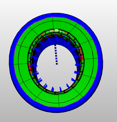
The orientation of the patches needs to be corrected so that Picker robot can reach the surface for the placement of patches.
There are two ways of changing the orientation of the patches:
- Change orientation
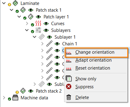
Go to Patch Artist and right click on
Chain 6.Select the option
Change orientationfrom the context menu.
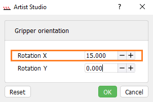
This will open a window for changing Gripper orientation. Enter here the value of
Rotation Xas 15.000 and click onOKbutton to save the changes.
For other chains, follow the same procedure as mentioned above. However, the user can also select multiple chains or patches for changing the orientation.
- Adapt orientation
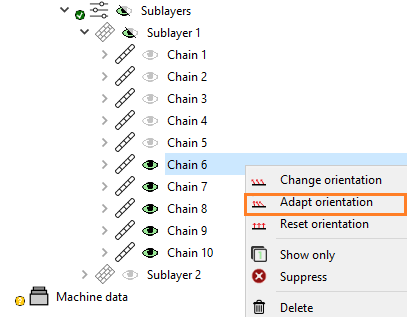
Go to Patch Artist and right click on
Chain 6.Select the option
Adapt orientationfrom the context menu.
Then click on the node as shown below for adapting its orientation and click on
 .
.
Follow the same procedure for other chains.
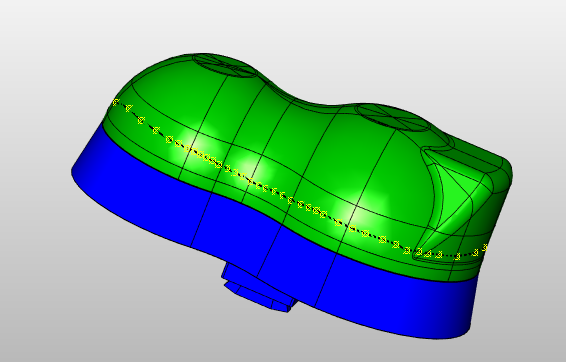
A.2.2 Create Boundary/Master curve
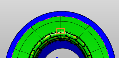
This part of the tutorial will explain how to create a Boundary or Master curve on the Gear box model step by step. However, it is not necessary to extract a boundary for a surface as Artist Studio automatically defines edge of surface as its Boundary.
From downloads,
Opengear_box.fpp which already has an extracted surface as shown below.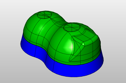
For creating a Boundary follow these steps:
Right click on
Shape extractionsand selectExtract boundary.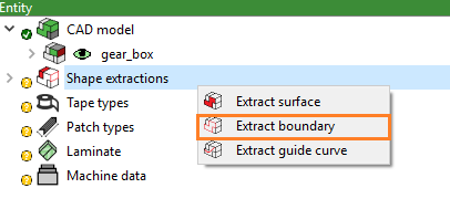
This will create a subitem
Boundary 1underBoundary.Click on the
Selectbutton either by clicking right on the created boundary or from Property window.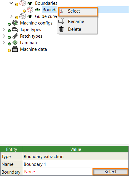
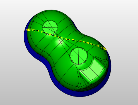
Extract a boundary by creating nodes on the surface. These nodes will join with the corresponding node to create a boundary.
Click on
button to save the created boundary.
For creating a Master curve follow the below mentioned steps:
Right click on
Shape extractionsand selectExtract master curve.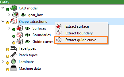
A subitem named with
Master curve 1will be created under the itemMaster curve.Click on the
Selectbutton either by clicking right on the created Master curve or from Property window.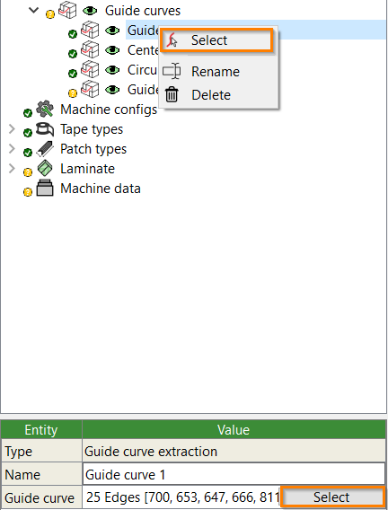
Extract a Master curve by creating nodes on the surface. These nodes will join with the corresponding node to create a Master curve.
Click on
button to save the created Master curve.
A.2.3 Rearranging the patches
The sequence with which the patches are placing can be customised to avoid large movements and complicated movements. Here, we will discuss how to rearrange the sequence of patches. Fot this part Open helmet.fpp from the downloads.
Go to
Motion artistand select the dataset you want to rearrange.Simply, drag and drop the patches to rearrange the sequence of patching.
A.2.4 Prepreg manufacturing process
The heating unit in manufacturing cell provides sufficient heating for resin of tape (on the gripper) so that it can be smoothly patched on the surface of the CAD model. However, some tapes can’t be heated using this heating unit as it might stick to the gripper. To solve this problem Prepreg manufacturing process in required. This process heats the tape externally with the of Infrared rays. The user can set the Prepreg heating time as:
Right click on the created
Data setand selectFill machine data set.
A pop-up window for
Data Generationwill appear.Go to
Prepeg Productionand enter the value forHeating timefor example: 0.5s.
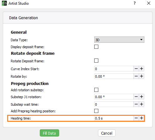
Finally, click on
Fill datato fille the data in the data set.